This discussion is locked.
You cannot post a reply to this discussion. If you have a question start a new discussion

MCB & Cable Size for 3 Phase Star (Wye) with Neutral

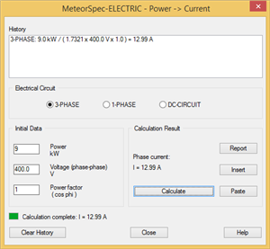
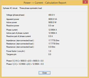
Hi, I'm trying to understand/figure out what MCB & Cable Size would be required for a 3 Phase 9kW Immersion Element wired in Star using Neutral?  I have been a little confused by the results when using various online calculators. One example here: https://www.watlow.com/resources-and-support/engineering-tools/3phase-delta-wye-calculator

i.e. Using a Line Voltage of 400V equals a Phase & Line Current of 12.99A.  Where as using a Phase Voltage of 230V equals a Phase & Line Current of 22.59A?


My questions are:

1. Are these calculations correct?

2. What Amperage MCB would be required?

3. Would the MCB required need to be 3P, 3P+N or 4P?

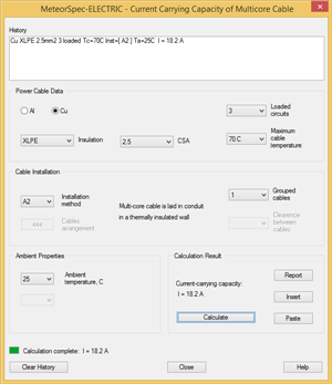
3. Would 1.5mm2 cable at a 6 meter run be adequate?


Thanks in advance for your feedback and help.
  • An aside aside.... as the water boils off the electrodes become insulated from each other until the tank refills with more water...

    Legh
  • Former Community Member
    0 Former Community Member
    Normal immersion heaters don't fall into that category at all.


    Yes, mapj1‍ also kindly pointed that out in his post. Had I looked a little further down the page from 554.1.2 I would have noticed this myself! Interestingly, 554.3 discussing immersion heaters doesn't mention 3-phase supplies.


  • Well any one immersion heater element only has 2 ends. so is intrinsically a single phase item. You may elect to run it on 400V of course if you want it to boil faster, and have 400v available 230V insulation to earth should be up to it ?.

    A 3 phase electrode boiler has all 3 phases in the water and no element as such. Same idea as these nasty devices not permitted in the UK. (nasty also in that your tea tastes sort of metallic )


    Not to be confused with the un-insulated element devices like this popular in less affluent countries. (skip to 5 mins in to see the elements,  and how the CPC earths the waterflow, after a fashion.) I have been assured these are perfectly safe on 30mA RCD so long as the water is reasonably pure. (and we worry about sockets in bathrooms....)
  • Same idea as these nasty devices not permitted in the UK

    A consumer version of the old "electrician's kettle" - i.e. a couple of nails hammered through a block of wood - the nails then connected to L&N and then stood on a mug with the other end of the nails sitting in the water/tea.

      - Andy.
  • broadgage:

    Yes, in the example given the line current will be about 13 amps. The exact calculated value will depend on whether 230 volts or 240 volts is assumed. The actual measured value will depend on mains voltage fluctuations and on manufacturing tolerances of the elements, what will be about 13 amps.


    A 16 amp or a 20 amp MCB would be fine. I would prefer 20 amps because under worst case conditions the load current might be  about 15 amps if the "3000 watt" elements were actually 3,150 watts due to manufacturing tolerances, and if they are designed for 230 volts and if the actual voltage was 250 volts.


    Cheers.  Assuming I went for the 20A MCB, would I then need a 32A Socket/Rotary Isolator?  Or would a 16A Socket/Rotary Isolator be suitable?


  • A well made 16A model or a cheap and cheerful 20A are about the same internally. Either would do. Avoid the cheapest of the cheap from no name internet sites -  when it comes to decently made contacts and solid mechanical parts you tend to get what you pay for. Do you need the kind you can lock off for maintenance and does it need to be safe with wet hands  ?

    (example )
  • Former Community Member
    0 Former Community Member
    If you use convenient calculation tools, the task is very simple.

    Load = 3 Phase Immersion Element
    P = 9kW
    Line voltage (phase-phase) = 400V
    Cos phi = 1.0
    Phase current = 12.99 A
    72fbda1d0ca232491d8e079665dcd319-original-meteorspec1.png


    The current carrying capacity depends on the installation conditions.

    d36e50d772f9cf31573f42dc2ca9ce69-original-meteorspec2.png

    Cable selected = Cu 2.5mm2  3p+N, 

    Protection = MCB 3x16A


    and calculation report:
    9ada74f9820e035a90fdafce5dd77c48-original-meteorspec3.png


  • Former Community Member
    0 Former Community Member
    Continue to select a power cable.
    You need to perform the following steps to complete the selection of the preselected cable and the protection device for it:

    - calculate the minimum SC current at the immersion element. The calculated minimum SCC (rms value) allows to verify disconnection time of the MCB.

    - calculate of voltage losses in the power supply line from the transformer to the consumer, taking into account all loads of the feeder.

    - calculate the maximum initial SC current and the peak short-circuit current at the end terminals of the MCB. The calculated maximum SCC (rms and peak values) determines the breaking capacity and the making capacity of circuit breaker.

    05bb7be47c5d5f8caf42b7cd5ee8796d-original-meteorspec4.png


    Of course, the above calculations can be performed only if the parameters of all elements of the supply circuit from the power transformer to the consumer are known.
    f8e23c5d4fa8cb5bf2c8062add2b938e-original-meteorspec6.png


  • calculate the minimum SC current at the immersion element. The calculated minimum SCC (rms value) allows to verify disconnection time of the MCB.

    Where is the c.p.c. described? Without that information I don't see how you can calculate the minimum fault current. Or is there a presumption that the c.p.c. is identical to the live conductors (which is probably not a safe assumption given many of the UK practices).

       - Andy.
  • Former Community Member
    0 Former Community Member
    To Andy


    The last image in my previous post is for informational purposes only. It illustrates a possible calculation procedure and calculation results at the end consumer. With this, I wanted to explain to the author of the question that the choice of a cable and MCB does not end with calculations of the load current and checking the CCC.


    As I wrote above „calculations can be performed only if the parameters of all elements of the supply circuit from the power transformer to the consumer are known“.  Using the calculation software, the user must simulate the entire circuit for the short-circuit current, including the transformer (with SC-impedance of MV-network) and all cables up to the estimated point.  Of course, I don't have this information.