This discussion has been locked.
You can no longer post new replies to this discussion. If you have a question you can start a new discussion

Ever thought about ... ?

I was asked a series of interesting questions this week about fault protection and overload protection for a particular application. Some of these really make you think, and the physics doesn't always lead you where you think you'd go.


Dropping out of all this, was me pointing out something interesting which I wonder whether it's ever crossed the minds of contributors to this Forum ... so here goes.


Ever thought about what, in typical UK installations, protects the electronics in a plug-in [to a standard BS 1363-2 socket-outlet] phone charger / wall-wart type power converter against:

(a) Fault current (consider both cases of L-N and L-PE); and

(b) Overload current ?


  • Thanks Graham - that looks similar to my earlier attempt. I'll give it some thought...


    Superficially though it doesn't look too bad against the figures I've got for MCBs - at 3kA

    B16 15,000A²s

    C16 18,000A²s

    C20 22,000A²s

    B32 18,000A²s

    (which also suggest a 1.0mm² conductor (with a k²S² of 13,225) isn't protected)


    I understand that our continental cousins typically prefer C types for their socket circuits - so if anything our B32 look like a better choice.

        - Andy.


  • HOWEVER this is NOT the case for BS1361, BS88, or BS 3036 rewireable fuses, with BS 3036 being perhaps the worst-case let-through.

    Interesting. Do you have numbers for BS 3036 fuses? (I (or rather Google) have failed to locate any so far).


    Given that the permitted Zs values for a rewireable are if anything a little higher than for either a BS88-3 (e.g. according to table 41.2) I would have though BS 3036 ones would have if anything slightly quicker disconnection times for the same current than an BS 88-3 and therefore (broadly) a lower I²t.


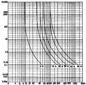
    Thanks, Andy, for the comment a couple of days ago with BS3036 I2t inferred from Fig 3A2 of BS7671. And Mike for the link to melting resistors: it's a good approach for keeping thecurrent low so it's easy to break, and I hadn't seen this component before. Over the weekend I had some login trouble with the IET site so I didn't get a chance to reply earlier.  I agree (Dave) that values of even 2 kA would be unusually high among all the installed population of sockets, and that faults in the electronic parts themselves could be made self-handling.  How many designers actually do consider this, even for a high current circuit with a slow protection device, and what do product standards require? Some wall warts I've seen are well sealed internally.  Others do have capacity for flying leads from pins to PCB to become loose and touch. I've seen cases of loose leads, probably after dropping. I'm not confident what worst case would happen for arcing duration with a strong source. Teenage memories of shorting a BS1363 plug, putting some strands of copper wire across its fuseholder, plugging it into a cooker socket (BS3036, 30A) and turning on with a stick, are that the arc in the plug blew itself out without blowing the fuse, though it left plenty of sign of its presence. That makes me more confident than I'd otherwise have been about the wall warts, but not that it would always be ok with internal arcing. 


    Anyway: the following is about the semi-enclosed fuses, which I and Graham seem to have assumed would do worse than many other devices. Is that justified...?


    I did, finally, find the text of BS3036. In it I see no requirement on let-through, nor on the detail of the time/current curve. It requires a fusing factor not greater than 2. And that the manufacturer shall provide a time/current plot over a range at least including 5% above the minimum fusing current and the 0.5 s fusing current. It's a far less tight specification than is found in standards for modern cartridge fuses, which typically require a t/I curve to fit between specified points, and total and pre-arcing let-through to be within some limits. Of course, a manufacturer could provide further specifications for semi-enclosed fuses, such as let-through versus prospective current, but I haven't found any example.  


    Fig 3A2 in BS7671 mentions 'maximum' disconnection times. The times given actually look rather low even for just the melting time. BS7671 Table 533.1 shows 0.85 mm diameter tinned copper for a 30 A fuse, whereas I need to come down to about 0.80 mm copper if calculating adibatic melting of the wire in 0.1 s with 450 A. Perhaps the tinning is expected to be thicker than the few-micron sizes I saw in references about other tinned copper. 

    The time that BS3036 wants used in manufacturers' time/current plots is the pre-arcing time. An appendix in BS3036 gives an example oscillogram from operation on 'moderate prospective current', in which arcing continues for 2 cycles with little reduction in current. So it seems the arcing period shouldn't be considered negligible in its effect on duration and let-through when one comes into the hundreds of amps range (which is the range I assume the plot means: low enough to have several cycles for melting, but high enough to have significant arcing). This fits with what I'd expected for semi-enclosed fuse operation in short circuits. Yes - melting times of fuses tend to a constant let-through at high currents. And good quality HRC fuses don't add much arcing let-through at prospective currents so low (by their standards) as 1 kA. But a couple of cycles of arcing of a semi-enclosed fuse at 1 kA could mean another 40 000 A2s just from the time of arcing. I'd risk a guess that the arcing period would not get shorter for higher current. If we move towards the 6 kA case mentioned earlier, the BS3036 fuses would be out of their depth, and presumably the let-through could be the value for the upstream cutout. In contrast, a good cartridge fuse or modern MCB will typically cut the current in a half cycle or less. This is partly why I'd (still) expect the semi-enclosed fuse to have high let-through at currents such as 1 kA. Also, because its element doesn't have the carefully formed restrictions of a cartridge fuse, I'd expect it to be a good deal slower at melting when coming up to the 1 kA level. Unfortunately, there don't seem to be specifications for BS3036 fuses at these higher currents that give times <0.1 s, and even the BS7671 value for 0.1 s may be rather low and not include arcing time. 


    As you'll see, this is mainly curiosity about how BS3036 fuses really behave, as an aside to the wall warts.  Having become used to diazed fuses, which are about 5 for a pound, always rated for prospective 50 kA, and with a nice low fusing factor like 1.45, I'm a bit suspicious of the venerable semi-enclosed things. 


    I don't remember having met a 45 A BS3036, but I see they existed, so perhaps there's somewhere a BS1363 socket on a cooker controller with such a beast behind it.  


  • I'd expect  the data for semi-enclosed fuses to be a bit variable - the whole point is they use fuse wire made to a certain tolerance, by anyone of a number of suppliers, placed in the holder by hand, and the finer  details of how the wire is tensioned, and may or may not be in contact with the ceramic carrier are outside of the control of the spec-writers.

    To compare the modern cartridge fuses have elements that are more like a stamped ribbon, with necks to create multple break points, to break up any arc, and M wells of softer metal to handle overload.

    There are (were) a number of fuse designs claiming to meet BS3036, that had various maximum current and PSSC options, though  the common Wylex ones went up to 45A (green spots) for cookers, but had a PSSC of 2kA, the older ones were 1kA. I understand that they will break considerably more without damage to the fuse holder or the unit, , but the limiting factor is the ejection of hot metal out of the ends of the holder in a way that would injure anyone inserting a fuse against a fault. I do not have the standard, but  I presume a version of the MCB not singeing the cheese-cloth test could be used to verify this, though if  such modern thinking pre-dates that standard I don't know,.
    75fb95ee2daad3e19ce4128e72b43984-original-bs3036_1992regs.gif


    And wylex_plugin_mcbs_datasheet_.pdf

    suggests some permitted Zs for 5sec and 0,4 seconds that are similar,.

    Of course, unlike an MCB, where the step from instant operation to slow thermal is a cliff edge, with a fuse it is less serious - if you get it wrong it opens in 0.5 seconds instead of 0,4, and most folk won't care.


    The old sweats advice was always to use the flat cap as an impromptu  'mitten' when inserting fuses into a board that may be live, just in case it arced. I guess a burn mark on the twill is less serious than damage to fingers, and in the same league as a pipe burn on the sweater form smoking while distracted - a thing from a bygone era.

    The fact the the BS1361 (or BS88-3) company fuse does not normally blow (even a 60A one) against a BS3036 30A, allows us to put another upper bound on the let-through energy of the old hot-wire fuse - even if it has been rewired in paperclip, the company fuse imposes an upper bound.

    regards Mike.

  • Triton tell installers not to connect a shower to a rewireable fuse, because they do not provide close protection and to swap them out for a BS1361 cartridge fuse and holder.


    Back when I did 16th Edition course I was told the Wiring Regulations like cartridge fuses. For a circuit like a shower circuit a fuse is probably a better choice than a MCB, just because it stops someone from immediately trying to reenergise a faulty appliance by just resetting a MCB.
  • Cheesecloths etc...  No sign of anything so modern in this 1958 masterpiece.  The concern appears only to be that the ejected material shouldn't cause arcing to a metal enclosure or to neighbouring fuses on other phases.  Part of the test is a fine wire connecting a metal enclosure to the 'suitable point' of the source (e.g. neutral) - this wire mustn't melt. 

    Probably the user was supposed to turn off the switch, change the fuse, and turn on. A cap sounds a good start if going the quicker route without switching off.


    The upper bound set by a service fuse can be a bit misleading, but it should be good for currents in the several kA level and up.  If we take, e.g. this bussman service fuse spec we'd find that the melting (pre-arcing) I2t for their 60 A service fuse is about half of what Andy and Graham have shown as lower bounds for the 30 A BS3036 based on t/I curves.  This makes sense because the values are for different timescales, and the cartridge fuse varies in I2t between these timescales.  The quoted I2t is for short times such as 10 ms. If one uses t/I curves from the same spec to calculate I2t for longer times, the result increases to about 4 times as much at 200 ms. The restrictions (necks) in a cartridge fuse element allow the bend of the t/I curve at short times to be designed. A fast fuse (semiconductor) has short but thin restrictions that can melt very quickly at one current, but can conduct their heat away to the surrounding element at rather lower current, whereas a general-purpose one has thicker, longer restrictions. Meanwhile, the simple cylindrical wire of a BS3036 fuse gives no control over the t/I curve for times at which heat transfer from the element can be neglected, which for a 30 A size would be times up to several hundred milliseconds: over this range the melting needs roughly constant I2t.  Cartridge fuses overtake the simple fuses in speed at the higher currents, because the shortness of their restrictions means that one has to come down to only milliseconds or tens of milliseconds before the melting I2t becomes roughly constant.  As long as most faults that pit a smaller BS3036 against a bigger cartridge fuse have rather low current, e.g. 1 kA or 500 A due to typical impedances of source, cable and possibly fault, the bigger fuse survives. But at higher current there comes a point where the curves will cross unless the cartridge fuse is much bigger or is designed for slow blowing.
  • Part of the test is a fine wire connecting a metal enclosure to the 'suitable point' of the source (e.g. neutral) - this wire mustn't melt. 

    How funny it is that the world joins up round the back.

    This reminds me of a problem I was involved with at one time.

    Large transmitter valves ( really big like 10kV of HT and 5 amps of anode current, with DI water cooling holding off the anode voltage accross the hoses) occasionally flash short and this is blamed on passing cosmic radiation, or  some other ill-explained effect. If the supply has too much decoupling capacitance, then the high surge currents mean chunks are blasted out of the cathode when this happens, and the device is quickly destroyed. So various fast shutdown crowbar circuits with thyratrons and later SCRs have been developed combined with the option of a series 1kW fire element, as a permanent kilowatt to sweat, but a to act as a known limit to what we would recognise as PSSC.

    So how do we know the protection circuit functions as expected.

    How to test it without risking that device worth more than my car ?

    In an Eimac application note written in the era of pipe smoke and slide rules when such transmitting valves were new, came a suggestion for those of of sufficient MF not to be afraid to run the kit with the lid open.


    An insulated rod may be used to introduce a length of earthed 5A fuse wire to form a short circuit between the energised anode and the casing. If the protection circuit successfully limits the discharge to a safe level, the fuse wire will remain intact, and the supply will shut off gracefully and be ready for a restart.

    Well mugger be, that's not one for those who are not fully confident in their design is it? if the trip does not operate you get blasted with ex fusewire ....!!

    We dragged this technique into the late 20th century with an HV relay and a better defined fuse rather than holding an insulated prodding stick by hand, as even with gloves and goggles it just felt wrong. In effect the test  measures the let through or I2t of the shutdown mechanism as being less than the fusing energy of the test fuse, though it did not say so.

    I now wonder if the folk who wrote it knew of each other's use of the method.

    regards

    Mike.
  • AJJewsbury:

    Thanks Graham - that looks similar to my earlier attempt. I'll give it some thought...


    Superficially though it doesn't look too bad against the figures I've got for MCBs - at 3kA

    B16 15,000A²s

    C16 18,000A²s

    C20 22,000A²s

    B32 18,000A²s

    (which also suggest a 1.0mm² conductor (with a k²S² of 13,225) isn't protected)


    I understand that our continental cousins typically prefer C types for their socket circuits - so if anything our B32 look like a better choice.

        - Andy.


    Those figures look like they're from the standard ... but the Type C ones are too high at 3 kA


    The figures for let-through at 3 kA fault current, from the current standard are:


    • Type B  ≤16 A - 15,000 A²s

    • Type C  ≤16 A - 17,000 A²s

    • Type B > 16 A ≤ 32 A - 18,000 A²s

    • Type C > 16 A ≤ 32 A - 20,000 A²s


    In reality, mcb's will have let-through much lower than BS EN 60898 / BS EN 61009.


  • Your analysis of the transformer design may be correct Mike, but the "excuse" that it needs this capacitor to save a small number of pennies is not satisfactory. The interwinding capacitance of this transformer could be designed to be a few pF, and the leakage inductance small with a slightly different philosophy, but I admit it would be slightly more expensive. When I buy a product that costs the best part of £1000 or so I do not expect someone to have made it less safe for the cost of pennies. That is the real point I was making, and it is important. Fitting two capacitors in series is a bodge, if one may fail, so may two! Tingles are unacceptable for a class 2 device, however it measures. It is also worth realising that class Y capacitors are not cheap.