This discussion has been locked.
You can no longer post new replies to this discussion. If you have a question you can start a new discussion

BEAMA guide to CB/RCBO selection for use with LED lighting


BEAMA have produced a guide to CB/RCBO selection for use with LED lighting, found here:
https://www.beama.org.uk/resourceLibrary/beama-guide-to-circuit-breaker-selection-for-led-lighting-.html
  • Well spotted. Suggests no more than about 500w worth of LED fittings on a 10A B type,  or more like 3 times than on a C type.

    No mention of the UK standard of 6A in either B or C type sadly.

    Also of interest is the quoted response of typical MCBs to very short duration surges, down to about 50usec. This is not something in the normal datasheets, but is potentialy very useful.

    This is not the fault breaking time of course, just the time that will get the release mechanism beyond the point of no return (de-latched)

    Interestingly  for the last order of magnitude of time we move almost exactly an order of magnitude in current too. Part of me wonders if many  intermediate points were measured, or if this really is a sharp change in power law and then  a straight line between 2 test settings.
    96cca9026db1be8433199252cdb98d65-original-mcbfast_response.png
  • Can we interpolate what a likely 6A B, C, D might be suggested?


  • I suspect we can, though it is not not quite a simple current scaling.

    Let us see what the curves are telling us.


    Firstly important to note that  the inrush problem is more serious when large numbers of small lamps are switched together compared to a few big ones.

    ( so 300W of 10W fittings may be the same inrush as more like 1kW of 75 watt ones - looking at the C10)


    Comparing 10A and 16A curves they give,and looking at the ends of the curves, we see

    15 *10W and 4*75W  for the B10 and

    These become

    22* 10W and 8* 75W for the B16


    30*10W and 5*150W for the C10

    These become 22* 10W and 8* 150W for the C16


    not quite 1.6 to one from 10A to 16  however -  15/22 is more like 1.4


    So I'd expect the 6A C type numbers to be more like 0.4 of the 10A ones, not 0.6 as you may expect

    I'd also expect a 6A B type to be troublesome with more  than about 50W of low wattage  LED loads ,. and therefore not recommended for very much beyond the smallest set-up.


    8aad423c99a4a6fd99579c393427fea1-original-10a-led_inrush.pnge670c41a0e1fcb00d07cf9f029312f77-original-16amcb_ledinrush.png

    M.
  • ebee:

    Can we interpolate what a likely 6A B, C, D might be suggested?


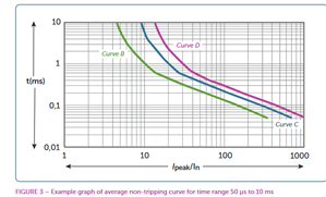
    You could use the second method (4.2) if I(peak) and t(H50) are available from the driver manufacturers literature. Using their example;

    For a 6 A ((In) MCB/RCBO and a load of 100 A LED driver peak inrush current (Ipeak) with a duration of 200 µs (tH50): using the chart above, Ipeak /In = 100/6 = 16.7 which correlates to 0.5 ms non-tripping time which is greater than the 200 µs peak inrush current time duration, therefore a Type B circuit breaker can be selected. If tH50 > 0.5 ms, a Type C or Type D MCB/RCBO would need to be selected.


    I have read here ADLT - LED Driver Inrush Currents Technical Paper that "The line impedance has a significant effect on the peak and duration of the inrush current." so that summing the inrush currents may not be appropriate. Not sure why this would be, might be voltage drop, but using a C or D type, would not only allow higher levels of inrush through without tripping, but due to lower Zs required in circuits protected by them to achieve ADS, lower line impedance would also be present i assume.


    Edit; I am also surprised that up to 3.5mA leakage current is allowed by BS EN 60598-1, per luminaire. Seems very high and would only allow a few luminaires to be fitted before RCD tripping occurred. I understand that there may be a few lamps per luminaire. But if your B-type RCBO started tripping, you changed it for a c type and it still tripped you might be scratching your head.


  • The line impedance that we assume to be small resistor of 1/PSSC or perhaps 1/Zs depending where we think currents are going is only really  correctly a low resistance at DC and up to 50Hz.


    A better model for faster waveforms is to consider the mains as the same low resistance but with an inductor in series . this inductance is partly the substation transformer windings and partly from the un-cancelled magnetic fields around the cables to it.

    The practical effect is that more  impedance is presented to higher frequency events (and can be a lot higher - at 300Hz (so a half-sine pulse would be  1.5milliseconds) the  reactive impedance of a transformer winding might be 6 times higher than it is at 50Hz) .

    The upshot is that the voltage drop associated with fat rising currents or high frequency harmonics is disproportionately high compared to measurements at 50Hz - or if you are fast enough you can load the mains and see the voltage dip far more than you expect, and then recover to the steady state value.


    At higher frequencies still (hundreds of KHz) the self capacitance of the lines conspires with the inductance to give you a more or less constant line impedance that  is several tens to a few hundreds of ohms depending on the cable construction.

    This is the ratio of current to voltage for fast events that are short compared to the propagation delay in the cable ( cable length and speed of light needed here, but 300m per microsecond is a good start), and in the short time that the source end not yet realised there has been a change at the load end.


    In short voltage drops you would have measured at 50Hz are greatly exceeded during the first few microseconds of a load step.

    Mike.