This discussion has been locked.
You can no longer post new replies to this discussion. If you have a question you can start a new discussion

Light reading

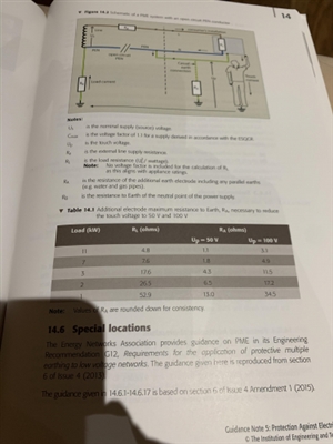
057333447b9d9089180dba9bdabb529b-huge-fc891021-69a1-4a15-a935-213b1a21c0d8.jpgJust doing a bit of light reading can someone explain this to me please.
  • Which bit, Table 14.1 of GN 5 ... or Figure 14.2 ?
  • If it is, I have a couple of pictures that might help explain what's going on in a slightly different way.


    First, PME system operating normally, with someone touching exposed-conductive-parts of Class I equipment outdoors:


    Second, when the Neutral breaks. Here hopefully you can clearly see what's going on:

  • You will find that diagram in several IET publications,  in the Electric Vehicle Charging Equipment Installation Code of Practice it is figure 5.1 on page 31 with this explanation on the preceding page.

    74cd90f14bc46eedd35cb1c305ac9733-original-20201219_101556.jpg
  • Next, the formula in section 14.5 is derived as follows:
    1. Assume the external source impedance is small compared with load resistances (this is roughly true, otherwise you'd have volt-drop issues).

    • The voltage across the earth electrode is the touch voltage, which can be calculated by Ohm's Law, VT=IbnREE in my illustration, or using GN5, it's UP=IbnRA

    • All we need to do now, is work out what Ibn is. If we assume the supply has a very low earth electrode resistance, we can then simply use Ohm's Law. We have the supply voltage connecting to only two resistors in series - RL and RA. In this case, is RL the resistance of all loads in the installation in parallel. Hence Ibn= UoCmax/(RL+RA)

    • If we put the expression Ibn for back in the expression UP=IbnRA, and rearrange, we get the formula shown on page 98 of GN5.


    Table 14.1 shows that, for different size load connected in the installation, in kW, what the required earth electrode resistance RA would be to achieve a touch voltage UP of either 50 V or 100 V. These are calculated using the formula on page 98.
  • My two questions are surely not much current would flow due to the resistance of earth so VT would be fairly small using the equation? 


    and where does 100v come from? 


    thanks Jack
  • First question


    Ohm's Law and the "voltage divider rule" tell us that the larger the resistance to earth, the greater the touch voltage.

    Since fatal shock current is measured at the most in 10s of mA, and load resistances are very low, even with very large earth electrode resistances in the extraneous-conductive-parts, is it now possible to see how someone can receive a fatal shock from this?

    Second question


    50 V AC is generally taken in BS 7671 to be a relatively safe touch voltage (some "zones" in special locations in Part 7 are obvious exceptions to that rule).

    100 V is used by DNOs as their "safe" limit.


    Section 722 uses 70 V for particular reasons (both hands-to-feet shock risk, large contact area, water-wet conditions, persons clothed and wearing shoes).
  • So that means the external resistance between the two earth electrodes would have to be pretty small? I know I’m a TT system we have higher touch voltages due to this issue of the earth being a high resistance
  • A good reason to have main protective bonding for without it, the chap in Graham’s open PEN situation might be subject to nearer full mains. The ongoing disappearance of metal service pipes is counterproductive in this regard although beneficial in terms of fault PDs within the installation. Maybe the foundation electrode proposal is intended to counter the former. It may also contribute to providing parallel paths for lightning current thereby spilling current away from SPDs.
  • MrJack96:

    So that means the external resistance between the two earth electrodes would have to be pretty small? I know I’m a TT system we have higher touch voltages due to this issue of the earth being a high resistance 


    Not necessarily. If the Neutral breaks, all the load current tries to go down the extraneous-conductive-parts back to the transformer. If this is resistance is about 100 Ohms, about 10 % of the current that would flow, flows through a person touching either exposed-conductive-parts, or extraneous-conductive-parts connected to the installation. Within the influence of the equipotential zone, the effects may be less. If the resistance is 1000 ohms, half of the load current will try to travel back through the person - certainly the equivalent will be a full Uo equivalent shock with no automatic disconnection.


    In TT systems, touch voltages within the influence of the main protective bonding are often far less than in TN systems, but outdoors, they approach Uo - this happens only in an earth fault, though, and is disconnected in a time according to Chapter 41. With a broken PEN, the only fault is the broken PEN - there is no fault in the installation - and not even an RCD will protect you.


  • So locally inside the installation the touch voltages should be small for a broken PEN conductor with installed main bonding only when in contact with the mass of earth can we see the touch voltages rising?