This discussion has been locked.
You can no longer post new replies to this discussion. If you have a question you can start a new discussion

Earthing of Neutral in Substation or MCB at LV Panel ? or both ?

Former Community Member
Hello everyone! 


Im having some doubts regarding where I should ground the Neutral and why ?


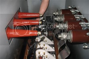
This is a new installation which is in an industry that will have its own substation 15/0.4Kv with a transformer of 1250KVA 15/0.4KV DY.


This substation will only feed the MainCircuitBreaker of the plant which is located 80meters away from the substation, there will be no other consumers from this substation/transformer.


The cables are already buried. They will be 6 cables per phase alluminum 240mm2 and 4 other cables 240mm2 alluminum also that could be used for neutral or PE or PEN depending... 


Should I ground the neutral the the transformer ? at the income of the LV MCB ? at both sides ? run only a PEN from substation or run Neutral and PE separate ?


These are the possible options i was considering.. and was hoping some of you guys give your opinions. 


Remember the distance between the TX and LV main panel is 80m
5fdf97a7ed1bff695edece754561095b-huge-whatsapp-image-2021-04-08-at-16.16.32.jpg

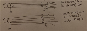
In the picture the PEN in option 1 and earth in option 2 is grounded at both sides (transofmer and LV mainboard) 


The other options would be as 1) and 2) but grounding only at one of those sides... (those would be pure TNS or TNCS)


Whats your opinions ?!


Thanks in advance!!


Parents
  • Sorry - as above the 'hot' / 'cold' thing is about HV side faults.


    In the UK the HV neutral is not distributed, there are just the HV phases, and underground HV will have an earthed armour, but not at zero impedance to the HV network, there may be current limiting by a neutral earthing resistor of typically about 1 ohm.

    So any HV  fault to earth has defined current of (say 6000A or less with that resistor of 1 ohm and 11kV phase to phase 6k6 to ground), and can be detected and interrupted promptly by what is in effect  giant sized RCD on the HV supply made from discrete current transformers and dedicated breaker firing circuits.


    On an overhead supply the fault current is generally limited further by the path through terra-frma,


    Once you know the HV fault current, you can look at the substation earthing arrangement and decide how much voltage rise an HV fault from say one phase to the transformer core would cause, and how long it would last for.

    This is where in the UK the DNO netork planners are are needed to advise.

    Then you can decide if you would dare to put that over-voltage onto the LV network. If the answer is low enough that it is safe, then the site is 'cold' and HV and LV earths can be combined.

    If not the site is 'hot' and HV earthing (the transformer core and case are considered at single fault risk of being live to  phase voltage, while the secondary windings would require multiple faults to reack HV voltage)


    The internals of a UK transformer keep the HV and LV sides apart and off earth.

    The photo below shows the details of typical connections - it's not my photo, but the flat 'ribbons' are the outgoing LV, and the thinner wires with the more insulated feed-through bushes are the HV side.


    regards Mike


    Edited to actually attach the photo this time - my apologies !!

    Normally this would be oil filled, and there would not be a human arm left in the tank when it is eventually energised  (!) - but it gives an idea of the size of the insulators and the arrangements..

    The main thing is that the 3 HV bushes coming in on the left, and the 4 (3 phases and an N) low voltage high current taking power out  the right . An earth goes direct to a bolt or stud on the outside I think this is a 500KVA (half megawatt ) unit, but the TX itself is out of view, to the bottom of the picture, and the wattage is not that important here - the thing  I want to show  is the neutral is as reliably isolated from the transformer and tank as the 3 phases, so HV and LV earths are very separate at this point.

    a4215d813526819371b441e34416e5b1-original-500kvasubstation_xformer.jpg


Reply
  • Sorry - as above the 'hot' / 'cold' thing is about HV side faults.


    In the UK the HV neutral is not distributed, there are just the HV phases, and underground HV will have an earthed armour, but not at zero impedance to the HV network, there may be current limiting by a neutral earthing resistor of typically about 1 ohm.

    So any HV  fault to earth has defined current of (say 6000A or less with that resistor of 1 ohm and 11kV phase to phase 6k6 to ground), and can be detected and interrupted promptly by what is in effect  giant sized RCD on the HV supply made from discrete current transformers and dedicated breaker firing circuits.


    On an overhead supply the fault current is generally limited further by the path through terra-frma,


    Once you know the HV fault current, you can look at the substation earthing arrangement and decide how much voltage rise an HV fault from say one phase to the transformer core would cause, and how long it would last for.

    This is where in the UK the DNO netork planners are are needed to advise.

    Then you can decide if you would dare to put that over-voltage onto the LV network. If the answer is low enough that it is safe, then the site is 'cold' and HV and LV earths can be combined.

    If not the site is 'hot' and HV earthing (the transformer core and case are considered at single fault risk of being live to  phase voltage, while the secondary windings would require multiple faults to reack HV voltage)


    The internals of a UK transformer keep the HV and LV sides apart and off earth.

    The photo below shows the details of typical connections - it's not my photo, but the flat 'ribbons' are the outgoing LV, and the thinner wires with the more insulated feed-through bushes are the HV side.


    regards Mike


    Edited to actually attach the photo this time - my apologies !!

    Normally this would be oil filled, and there would not be a human arm left in the tank when it is eventually energised  (!) - but it gives an idea of the size of the insulators and the arrangements..

    The main thing is that the 3 HV bushes coming in on the left, and the 4 (3 phases and an N) low voltage high current taking power out  the right . An earth goes direct to a bolt or stud on the outside I think this is a 500KVA (half megawatt ) unit, but the TX itself is out of view, to the bottom of the picture, and the wattage is not that important here - the thing  I want to show  is the neutral is as reliably isolated from the transformer and tank as the 3 phases, so HV and LV earths are very separate at this point.

    a4215d813526819371b441e34416e5b1-original-500kvasubstation_xformer.jpg


Children
No Data