You can no longer post new replies to this discussion. If you have a question you can start a new discussion
Reactance and impedance of 300 mm2 Aluminium 4-core cable
Former Community Member
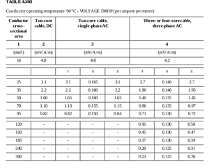
I am doing 6.3.4 example in the IET Electrical installation design guide: calculations for electricians and designers. in part 2: three-phase to earth fault current at C, it says a 100m of 300 mm2 cable aluminium SWA thermosetting (Table F7A). but the table does not have x value, only r value. where and how to find these values to help in calculating the prospective fault current ?
The quoted figures vary a bit from place to place - the degree of cancellation of the magnetic fields is core layout dependant - so the X part varies with cable make up in a way resistance does not, for example if the cores are circular or segmented shapes.
The resistive part is simpler as that only depends on core material and cross-sectional area, oh and temperature.
In a real design, the R may be lower if your design is volt drop limited as then the cores are cooler, so a hybrid result of the X of the 90C tables and the R of the 70c tables may be nearer to what you would see in a real world measurement.
Luckily for exams they just want you to understand the tables as they are.
Edit TABLE 4H4 A/B are for the 70C thermoplastic cables and are slightly different.
Here are some other numbers to conjure with
TABLE 4J4A/B
Multicore armoured 90 °C thermosetting insulated cables (ALUMINIUM CONDUCTORS)
Air Ambient temperature: 30 °C - Ground Ambient temperature: 20 °C - Conductor operating temperature: 90 °C- CURRENT-CARRYING CAPACITY (amperes):
Also another 'gotcha' is to be very clear if you are considering
1) a phase to earth or neutral fault (230V) or
3) a phase to phase fault (400V)
or
3) a phase to phase to phase fault - where if the 3 line currents are equal, the point of junction is a perfect neutral, and then it is 230V across the resistance from one live core only - there is no neutral drop The line current is then ~ twice the answer in case 1.