You can no longer post new replies to this discussion. If you have a question you can start a new discussion
Reactance and impedance of 300 mm2 Aluminium 4-core cable
Former Community Member
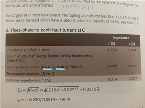
I am doing 6.3.4 example in the IET Electrical installation design guide: calculations for electricians and designers. in part 2: three-phase to earth fault current at C, it says a 100m of 300 mm2 cable aluminium SWA thermosetting (Table F7A). but the table does not have x value, only r value. where and how to find these values to help in calculating the prospective fault current ?
The quoted figures vary a bit from place to place - the degree of cancellation of the magnetic fields is core layout dependant - so the X part varies with cable make up in a way resistance does not, for example if the cores are circular or segmented shapes.
The resistive part is simpler as that only depends on core material and cross-sectional area, oh and temperature.
In a real design, the R may be lower if your design is volt drop limited as then the cores are cooler, so a hybrid result of the X of the 90C tables and the R of the 70c tables may be nearer to what you would see in a real world measurement.
Luckily for exams they just want you to understand the tables as they are.
Edit TABLE 4H4 A/B are for the 70C thermoplastic cables and are slightly different.
Here are some other numbers to conjure with
TABLE 4J4A/B
Multicore armoured 90 °C thermosetting insulated cables (ALUMINIUM CONDUCTORS)
Air Ambient temperature: 30 °C - Ground Ambient temperature: 20 °C - Conductor operating temperature: 90 °C- CURRENT-CARRYING CAPACITY (amperes):
Also another 'gotcha' is to be very clear if you are considering
1) a phase to earth or neutral fault (230V) or
3) a phase to phase fault (400V)
or
3) a phase to phase to phase fault - where if the 3 line currents are equal, the point of junction is a perfect neutral, and then it is 230V across the resistance from one live core only - there is no neutral drop The line current is then ~ twice the answer in case 1.
Note: The table being referenced here is F.7A in the Design Guide it is based on BS 6346.
I have an ealier version of the Design Guide which has basically the same question with some minor changes. Table F.7A in my book gives 0.08 ohms / km @ 20ºC for x as shown in the question solution. This is the conductor reactance (i.e. not the armour reactance). I assume you are aware that for a three phase fault to earth the armour will not carry any fault current as the the three phase currents sum to zero.
I found it. I have the 4th edition which doesn't have the x and r values for aluminum. Here is a snap shot of the 2nd edition. I was really lost for a whole day.
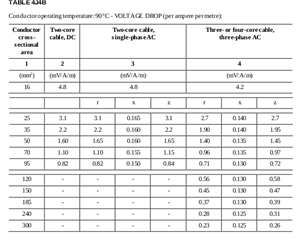
Note that those figures you have highlighted are not for voltage drops in SWA but relate to unarmoured cable with cores only.
In the case of the phase to phase to phase fault this is partly correct, as there is only voltage drop in the line conductors, not in the return path.
However, the X part is likely to be a bit off, as in the 3 core SWA, the magnetic fields of the 3 cores cancel, making the transmission line inductance rather less than the sum of the individual lines .
The question the OP is answering does not concern voltage drops, it is a fault current calculation based on an LV network given in the book mentioned.
As I stated above - Table F.7A is (partly) based on BS 6346 (Table H2).
The BS 6346 table only gives resistance values, in this case for PVC armoured cables with aluminium conductors. Table F.7A extends the BS 6346 table to included reactances values for the conductors and for the armour. The reactance values quoted come from other sources (look at The IEE Commentary on the IEE Wiring Regulations - take the x voltage drop from BS 7671 table 4H2B and divide by root 3).
The OP has correctly identified the parameters needed to answer the question in the "IET Electrical installation design guide: calculations for electricians and designers".
The similar book I have is the IEE - Electrical Installation Design Guide - ISBN 978-0-86341-550-0