This discussion has been locked.
You can no longer post new replies to this discussion. If you have a question you can start a new discussion

Unfused spur.

Hello All,


Could an unfused R.C.D. protected spur, from a complient ring final circuit, supplying a single outdoor socket via 1.5mm2 6242Y cable of max. length 300mm through a brick wall from an indoor socket outlet be considered compliant?


Z.
  • The good thing is that for those of us who work at the domestic end of the scale, a lot of this has been worked out for us.


    CCC in Table 4D5, etc. lets us know the maximum sustained load before cables get too warm. Match them to the appropriate OCPD and you get the energy let through. Finally, some kind soul has worked out the smallest necessary CPC that will cope with it.
  • The "instantaneous" part of the current curves for MCBs comes from the following:

    A short circuit high current fault occurs which generates a magnetic field in the trip coil. It exists for 1/2 cycle when the magnetic field collapses and is reversed. It could be that the short occurs partway through a cycle but we will ignore that for the moment.  1/2 cycle lasts for 10ms at 50 Hz. In this 1/2 cycle, the energy let through is the RMS current squared x 10 ms. A 6kA breaker then has 6kA squared x 10 ms which is 360,000 A²seconds. This number is not that given by the manufacturer, so what is wrong? They say typically 45,000A² seconds. The only variable to be incorrect is the trip time, which therefore must be substantially less than 10 ms. I² is 36 million Amps The let-through of 45,000 is divided by 36 million giving a trip time of 1.25 ms. I have deliberately simplified this as the waveform over a part cycle is not a sine wave, the worst case is a small section of the sine wave approaching the peak, the width of which is related to the trip time. As you see, all this is very complicated to exactly define and calculate, which is why one gets the worst-case figure from the manufacturer. In mechanical terms 1ms is very long, consider what happens inside a car engine during 10 milliseconds at 6000 RPM.


    Does this help you to see what is wrong with the graphs in BS7671, and more to the point why those for fuses are different?
  • Some feedback to the IET on whether these points are useful on the forum would be nice, the webinars are good too, but questions often start some new topics for many.

    Thanks to all contributors, thanks to Mike for the physics!

    Kind regards

    David
  • In this 1/2 cycle, the energy let through is the RMS current squared x 10 ms. A 6kA breaker then has 6kA squared x 10 ms which is 360,000 A²seconds. This number is not that given by the manufacturer, so what is wrong? They say typically 45,000A² seconds. The only variable to be incorrect is the trip time,


    Quite so - and the contacts start to open much faster than 10ms, start in quite a bit less than 1ms in fact- the 10ms will be the total extinction of the arc on the zero crossing, and compared to the PSSC, quite a modest current flow

    As soon as the contacts have opened even a little bit (and the same applies to blowing a fuse,more or less) an arc is drawn. This volume of gas and ionic plasma (atoms with electrons torn off and free electrons) is very far from a zero resistance - which is both good and bad - good in that the fault current is now quite a bit more limited if rather uncertain in value, bad in that all that energy is heating a very small and angry volume, so angry in fact that more atoms are ionised by impact, and the cloud of plasma grows rapidly - the plasma volume grows more or less at the speed of sound (not so surprising as that too is determined by the speed of atoms bumping into each other.)

    This can be seen as a series resistance whose value would fall with time if nothing moved as more plasma is made (the number of atoms ionised is proportional to the energy input, but that is like filling a leaky bath, as there is also  the recombination time, which is when the atoms and the free electrons getting back together again, giving off some light, one photon of light or heat per electron that clicks back home into its orbit .. ? well, very roughly  )

    But the contacts have not stopped moving (or the fuse wire burning back) and the aim is to stretch that thread of plasma, driving the voltage drop up. and ideally 'quench' it by letting it hit some large metallic mass that absorbs some of the energy as heat (and may get a bit cooked in the process - the impact damage from an ion beam leaves the surface looking like the moon at microscopic scale) If the plasma can be stretched faster than it can grow (and the rate of growth is nothing more than the available energy as V*I) the resistance will not fall, and the current stays high-ish but acceptable until the next zero-crossing, when it goes out (not an option for DC, so bigger gaps, maybe supersonic contact speeds,  and more arc catching metal work...)

    Really big contactors, the ones with a winding handle or a motor for a firing spring that makes your toes curl to think of the stored energy, often have 2 sets of contacts in parallel, a clean set that open and shut while the other contacts are still connected, that never get arc damage, and a smaller working set of contacts that suffer all the flash and pop, but mean that the clean set only ever open and close with very small contact voltages.

    Other tricks include deflecting the ion beam of the plasma with magnetic  fields  so that it burns some less important part of the mechanism.


    There is a lot to it hidden in an innocent rectangular box.

    M.


  • I have just thought of something else, why is the energy let through less for lower rated breakers, say 6A? The energy needed to operate the mechanism is probably the same for all ratings, so the 6A one needs to get the same magnetic field from less current. This requires more turns of thinner wire, exactly what one will find if a few are dismantled, The energy let through is less because operation will be faster with the fault current allowed and more turns. In principle if one makes the coil have more turns the energy let through can be set as required, the constraint is then the space available and the acceptable energy (voltage) loss across the coil inductance. Some manufacturers do have physically larger products available for less let through energy. Inside MCBs are fairly crowded if they fit the usual profile, thus BS 80898 ratings with minor deviations.
  • OK, you've just about convinced me that Z's MCB will open quickly enough at a few hundred amps to save the 1.0mm².


    I think we still have a difficulty in deciding how far this protection goes as the fault current increases though.


    Hopefully we're all agreeing with k=115 and to we need to keep the energy let-though below 13,225 A²s to meet BS 7671's requirement to protect the 1.0mm² and the associated insulation.


    If the fault current was as high as 3,000A then the data from BS EN 60898 seems to say we do have a problem as it says the energy let-through is 18,000 A²s.


    Could I just take 13,225A²s and work backwards from I²t using 0.01s and come up with 1150A - or is that an over-simplification?


      - Andy.
  • Could I just take 13,225A²s and work backwards from I²t using 0.01s and come up with 1150A - or is that an over-simplification?


    That is exactly the sort of thing  you can do if you know  (or assume that) the breaking current waveform  is equivalent to a rectangular pulse of 1150 Amps lasting  10msec -  and the assumed temp rise in the copper may be say  from 70 to about 160 C - being the onset of irreversible changes to the plastic insulation when heated  without an atmosphere - which is true for the plastic surface  touching the copper.


    If you think the CPC is not at 70C when the fault comes on, and that is probably more applicable to a CPC that is in singles, not in the main cable

    then you can  take  a bit more, perhaps from 30C to 160C

    M.
  • Actual MCBs that aren't antique tend to operate on high currents in well less than a half-cycle, as has been suggested here already: they are "current limiting", so they can force the current to a zero before its natural zero-crossing.  But the wiring regulations give the curves going down to 100 ms (not 10 ms). Presumably that's because it's all that can be guaranteed for an MCB according to the expected product standard.  In my ~20 year old copy of IEC60898 I see no requirement to be quicker than 100 ms for any fault current; no requirement on let-through either, except that a specification of it should be available to the product's user.  So if you go only by what the standard requires, the let-through could be absurdly high.  It's necessary to use the manufacturer's let-through specification to avoid depending on the 100 ms assumption, but I don't see what the regs can improve if  the product standards don't specify more.

  • Many thanks to all valued contributors on this fascinating subject. I have just watched the film "2010 The Year We Make Contact" but that does not even compare to the mind blowing information posted here. I am punch drunk after reading these recent posts. So many valuable and insightful comments. Thanks so much.


    Truth is definitely stranger than fiction.


    Off for a little lay down.


    Z.
  • Nathaniel:

    Actual MCBs that aren't antique tend to operate on high currents in well less than a half-cycle, as has been suggested here already: they are "current limiting", so they can force the current to a zero before its natural zero-crossing.  But the wiring regulations give the curves going down to 100 ms (not 10 ms). Presumably that's because it's all that can be guaranteed for an MCB according to the expected product standard.  In my ~20 year old copy of IEC60898 I see no requirement to be quicker than 100 ms for any fault current; no requirement on let-through either, except that a specification of it should be available to the product's user.  So if you go only by what the standard requires, the let-through could be absurdly high.  It's necessary to use the manufacturer's let-through specification to avoid depending on the 100 ms assumption, but I don't see what the regs can improve if  the product standards don't specify more.


    As an historical note, if you go back to the earlier editions of the wiring regs (e.g. early 16th Ed - probably just before it became BS 7671) - the full curves are there for MCBs.

    I haven't checked, but I suspect that change coincided with the advise to use energy let-though data rather than "time" when calculating for the adiabatic once you reached the magnetic region of operation. As Mike mentioned, "t" gets a bit wobbly with short disconnection times as a lot then starts to depend on quite where in the a.c. current cycle the fault appears - as if it all starts in the wrong part of the cycle there may be quite a delay of a portion of a cycle until the current gets high enough for the magnetics to kick in - even though the effect on the overall energy let-through is small.


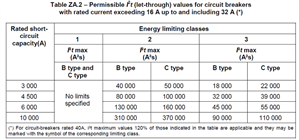
    It sounds like BS EN 60898 has changed a bit over the years. They copy I've seen had an Annexe ZA with various energy let-though figure. Oddly (and annoyingly) they're keyed on rated breaking capacity of the MCB rather than the actual fault current. Most are energy class 3 these days I think.


    (hopefully it's within the copyright rules to use a couple of small extracts for academic discussion..)
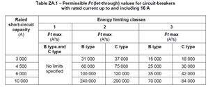
    79657ba9d9a9f92067d1c42b822deeca-original-mcbi2t16asmall.png
    89c79c8d3d6053f84bd6ea46f5a31a18-original-mcbi2t32asmall.png


      - Andy.