This discussion is locked.
You cannot post a reply to this discussion. If you have a question start a new discussion

Two phase three wire

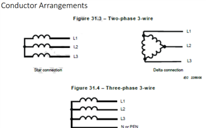
BS7671 shows diagrams of  system types and earthing arrangements in the UK. Even a person fully converstant with the jargon would wonder why its sister version ROI have added two additional  diagrams. maybe it is just up the pole or ground mounted supply transformers that they are  shown for information 


Chapter 3 Fig 31.3 of I.S. 10101: 2020 National Rules for Electrical Installations shows these diagrams if you + +  and move across to centre of computer makes it easy to read.


ciftraining.ie/.../Presentation-for-Download.pdf


www.eeweb.com/.../


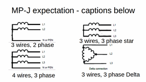
The NEC (National Electrical Code) the bible of the electrical construction industry USA,  has a nice description- Polyphase circuits. Circuits running on AC and having two or more, interrelated voltages, usually of equal amplitudes, phase differences, and periods, ect. If a neutral conductor exists, the voltages referenced to the neutral conductor are equal in amplitude and phase. The most common version is that of three-phase, equal in amplitude, with phases 120' apart.

jcm   


  • I must admit, looking at the PDF, I wonder if there has been a slip-up with captions, or if I mis-unserstand their language.

    2 phase 3 wire to me is 2 lives and an earthed neutral, rather like split phase, or the building site reduced low voltage, though normally there are no loads from one live to the earth in that case, and  I see the top 2 as examples of 3 phases, 3 wires, and the lower as 3 phase 4 wire.

    It is also possible this is not the figure you were alluding to at all, and we are at cross-purposes.

    M.
    7fc5c25c290c6696b53ab6abac6dccc1-original-2-phase.png
  • Mike, those are the two diagrams (two phase three wire)I was refering to, they are not showing their correct relationship to an installation, I would think more detail should have been used.

    Thanks,

    jcm 

  • Indeed, and the presence of 3 wires called 'L', to me at least, would be expected on 3 phase, not 2 phase installations.


    I still think there is a caption SNAFU, and it should be as below, though I usually draw the star windings to indicate the phasor angles  when sketching by hand I appreciate that in the modern world of CAD angles other than multiples of 90 deg are hard to draw.
    63dc776553717699d03b1e8566f512d2-original-phases-wires.gif
  • It is not clear to me exactly what they mean by "two phase three wire"


    True two phase, with 90 degree phase angle between phases ? Never common and believed extinct in the UK or in Ireland.  BTW in a true two phase system, the neutral currents do not cancel each other out, the neutral wire needs to be larger than the phase conductors.


    Two phases and the neutral derived from a standard 3 phase 4 wire system. 120 degree phase angle between phases.


    Or do they mean what should be more correctly called SINGLE phase 3 wire, usually 230/240 volts between either line and the earthed neutral and with 460/480 volts between the two lines. Used in areas with only a single phase two wire HV supply.

    Also still existing in some urban areas including West London.

    This is also the norm in the USA for domestic services at 120/240 volts.