This discussion is locked.
You cannot post a reply to this discussion. If you have a question start a new discussion

Out out voltage of 3 phase inverter

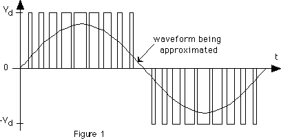
I’m trying to understand if we have a three phase motor 50/60hz what would we set the voltage at for the inverter?  If 50hz I can see it being 415 here in the uk but say if we was running the motor at 60hz can we up the voltage to say 480v? 


thanks guys
  • What is the intended load - US style 3 phase equipment comes in many voltages, far more than the 400V and 690V you commonly find here.

    Yes, a UK motor run 120% faster can take 120% of the volts if everything scales, but it probably will not need it.


    M.


  • This is the nameplate so I take it you’d set it to 440volts 60hz in delta just curious as the inputs 415volts
  • A rather odd feature of motors made in the USA, or intended for sale in the USA  is that they are rated for a bit less than the nominal supply voltage.

    This on the grounds that the voltage at the motor terminals may be bit less than at incoming supply.


    Common motor voltages include 115 volts, for 120 volt circuits.

                                                          200 volts for 208 volt circuits.

                                                          230 volts for 240 volt circuits.

                                                          460 volts for 480 volt circuits.

                                                and     575 volts for 600 volt circuits.


    All at 60 cycles. The most common voltage is probably a 460 volt motor for operation from a 480 volt circuit. 3 phase, 4 wire systems at 277/480 volts are very common in the USA.

    Small motors for domestic appliances and the like are often 115 volts for operation on a 120 volt circuit.
  • looking at the nameplate,
    059d6e83cb1ab04d14ec37f7c658389c-original-motorplate_crop.png

    I think 380-420V from 50Hz


    or 440-480 from 60Hz.


    However, far more seriously, given the mention of 660-725V in the star or delta box, it might be that the windings expect to see 400 volts or so between the winding ends,

    There are some variations on 690V supplies, options are 

    3 phases of 690v to ground (1k2 between phases),   (to be fair only seen this sort of 3 phases supply in German factory)  for that you will need a transformer, but that  is not a likely inverter output to be fair.

    or

    3 phases of 400v to ground (690 phase to phase) you wire it as a star, and it draws 6.18 amps per line (only see this sort of 3 phase this on large sites in the UK)

    finally , not 690 at all but most common (more like the UK street 3 phase standard).

    3 phases of 230v to ground, 400v between phases you wire as a delta and it draws 10.7 amps per line


    This sort of  marries up with the  5.5kw shaft power if we allow for some losses and power factors.


    3 lots of 400V at 6A is 400*6 *3 = 7.2kVA, more like 6kw  when you allow for the power factor.


    3 lots of 230V at 10.7A is 3_10*230 = 6.9kW, more like 5 and a bit with power factor.

    Mike


  • So the inverter input is 50hz 415 3 phase but capable of delivering 440V 3 phase 60Hz?
  • MrJack96:

    So the inverter input is 50hz 415 3 phase but capable of delivering 440V 3 phase 60Hz? 


    That's not really an inverter. I assume that we are talking about a variable speed drive. The variation in speed is due to changes in the output frequency - the waveform pulls the rotor round as the magnetic field goes round from coil to coil. I would be surprised if you have to set the output voltage, but perhaps you do. Would you like to give us details of the "inverter"?


  • Yeah sorry it’s a VSD Chris. My mistake
  • https://literature.rockwellautomation.com/idc/groups/literature/documents/um/22b-um001_-en-e.pdf


    this is the VSD
  • i presume the
    22B-E012x104   7kW unit

    or maybe the
    22B-E9P9x104     5.5kW unit


    Be aware that the output is not a sine wave, anything like, so the normal RMS voltage and current thing  will not read on most meters.

    really the incoming 3 phase is rectified to give a DC bus, and then fast switching transistors connect and disconnect with varying mark to space ratio, to give an average force on the coils equivalent, roughly, to a sine wave. (long bursts on and short time off to mimic the peak of the sine, and long off, short on to mimic the near zero part.)

    The chopping frequency is sometimes called carrier, after the radio analogy of modulation.

  • So set the inverter for 440v 60Hz?