What is experience of everybody on this?
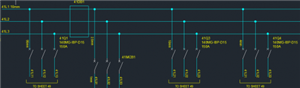
This particular application in design phase has an incoming 95mm cable in through a a switch disconnector which requires distribution to many smaller branch circuits. usually this application for me in control panels is simple as small currents (<30A) are in use but this larger requirement means the terminations get tricky having many different wire sizes.
Thanks Folks!