This discussion is locked.
You cannot post a reply to this discussion. If you have a question start a new discussion

Single Point or Solid Bonding query on 20kv U/G supplies

Hi Guys

I'm reviewing a MV cable installation design proposal and I'd appreciate some advice, scenario as below...

New Building with new MV switchgear being fed from an existing Main MV switchroom within the same facility campus.

MV distribution system is 20KV and there are 2 new supplies (A&B) to be installed to the new building.

New building total load is around 12,900 KVA and each supply must be able to accept full load.

Upstream breakers in Main MV switchroom are 1250A and the Incoming breakers in the new building MV switchroom are 630A.

The route between switch rooms is fully ducted (with cable chambers) and the distance is around 460m.

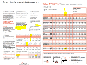
The current cable design is for 3x1c 185 AWA cables per circuit with AWA bonded at both ends and a separate 1c x 150mm CPC.

Cables to be installed in trefoil within ducts.

Current design has the MV terminations bonded at both ends


My question is; is double ended bonding suitable for this length of run or would there be potential issues with high circulating currents?


Regards, Seansasta
  • Is this a U.K. installation?


    if so are we talking about a 400/230V supply which we call LV not MV?


    Regards


    JP
  • PS


    Are you sure the cable run is 460m?


  • Hi John
    Installation is in EU and it's a 20KV distribution system. Yes the circuit length is 460m. MV/HV Cables are single core copper conductors with AWA.

    thanks

    Seansasta

  • you will get currents circulating along one armour and back down the other two, if all the armours are glanded to common chunks of metal at both ends.  Which way it flows will rotate in step with the primary phases. Make sure the votage drops and current ratings you use allow for this armour loss - the  figures in UK standards do, but I am not sure this is the case in all countries. If you only bond one outer and use insulation glands on the rest, you will introduce an earth voltage offset. It is possible to reduce this problem by swappping links between the armours around at intervals along the cables, but it is not normally worth it at 50Hz, it is easier, and at 20kV safer, to take the hit of the modest extra loss.

    previous similar discussion (for LV but the amps do not care about that....) 

    regards Mike
  • Thanks Mike

    I've checked the Nexans data sheets (see snip below) for the current ratings of the cable supplied and from what I can deduce an adjustment would need to be made to account for the type of bonding used on the cable screen; I'm just not clear on how to calculate that value or is there a rule of thumb factor? I'd prefer to stick with solid bonding, just not sure how much of a de-rating factor this would have in this case? The 3 single core cables are to be pulled into a single duct (1 duct per circuit) and the earth cables in a separate duct alongside. 
    8e43ccff1c30c7f029907567eee7f8ef-original-image.png
  • at 50Hz, depending on how the singles are laid you will get perhaps (400A * 400m * geometry factor)  maybe 10 volts along the length of the armour - imagine unbolting one gland and measuring voltage across the open gap ( the rather unknown geometry factor means you could see  between  lowest maybe  5v   if you had the cores as  a tight and rotating trefoil, maybe as much as 20v if phase cables are widely spaced on ladder and form a large area air cored loop). Just imagine as a thought experiment, please  do not actually undo a live gland  !!!


    We know the resistance of the armour, and the parallel CPC path, and we can calculate the amps that will flow round the loop from that driving voltage. This tells you how much heat is lost in pushing current in an endless loop of armour.  Compare that to the expected loss in the cables from current times resistive voltage drop, and you can see what a fraction it is. You will also see why too thin metal gland plates can run hot from this loop current, as well as steel ones running hot from magnetic loss.

    To run cool the cross section of the metal between glands needs to match cable cross -section,  so a fairly chunky gland plate or tails are needed.

    The ratings for AWA trerfoils  in the annex of BS7671 are for the both ends solid bonded case. Moving to a single end bond and flying CPC allows you to up the core ratings a bit.
    this nexan data (see page 11 for example) also has the note  'solid bond' in the top row of cable layouts for the various ratings where this applies


    If you get stuck I am happy to help review/ check  sums when I have some free time. With  the caveat I'm as likely to make an error as anyone but the chances of both of us making the same one is reduced a bit.


    M.
    wiring matters article

    more background intro
  • Thanks Mike - this is a good help, much appreciated

    Rgds,

    Seansasta