This discussion has been locked.
You can no longer post new replies to this discussion. If you have a question you can start a new discussion

SPD(s) for an outdoor TT install

Good morning


I am trying to get my head around surge protection - the *basic type and positioning* really- and taking an example situation please where surge protection may be added:


A moorland, overhead supplied, residential property; TN-C-S.


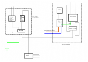
Outdoor regular wall meter cupboard in which is the DNO head, meter and some existing consumer switchgear (been as it is for over a decade with RCDs, MCBs from when the supply was TT) in an enclosure fed via a supply splitter block [henly] , which is there to supply two consumer units each at either end of the property.


Also fed from the splitter block, a supply to another nearby enclosure in which resides switch gear for TT outdoor services - lamp columns and electric gate 30ma RCBO final circuits and a  RCD type s distrib circuit to a 'garden work pod' which has a little sub-board.


(rough block diag attached to help description)


1) What would be the positioning and type of any surge protection  (where there is no LPS on the building rightly or wrongly)   ?


my questioning thoughts on this:

- near the origin (as in the source of energy) a  Type 1 as it is overhead fed, but not sure if CT1 or CT2 connection 

- in the consumer units a type 2  CT1 connected

- for the TT outdoor final circuits a type 2  , does this have to be upfront of RCBO being TT and  CT1 or CT2

- for the TT pod  distrib circuit, a type 2 and none  in the 'pod' sub board, or  none and type 2 in the pod subboard


- does the outdoor TT install even require SPD; can a 'surge' propogate back uptream into other parts

- future considerations, if alterations made e.g.


2) Lastly, is SPD simply about protecting connected equipment, or is it also about protecting  conductor insulation from voltages that might damage it ?


It does seem that adding type 1 SPD at the 'origin' (in meter box - other one is possible)  into this situation is nigh impossible without major works, so unless its possible to simply add it to each consumer unit/subboard as such... it seems academic, but still   it would be interesting to know where it should go ideally.


Regards

Habs


(perhaps one's ambition outweighs one's abilities)

7b9cf34fb3da18dccd3044d711131e43-huge-ietwrforumspd1.png


(last para edited for clarity ... well that was the intention)
Parents
  • Ah right [with furrowed brow]. Therefore drawing on comments and just for further exploring the subject...


    In the example installation, if working with current switchgear, where would the type 2's be positioned ?   - Btw, I'm not asking for a design here, it's just exploring a learning curve for me?


    If a Type 1 is not necessarily needed, are there 'cascading/coordinated'  type 2's  to allow them to be put in at each consumer unit/db position (one of the house CUs is 25m away) and one at the origin ?


    On the TN-C-S side of things and if one of the consumer units is 20m or so from the intake position, then would it make sense to put type 2 in the CUs with nothing at the main intake (its outside and limited switchgear to sacrifice) connected up CT1 ?


    On the TT side, Type 2 connected CT2 infront of  the RCBO final circuit board and 100ma type s distrib (or perhaps a type 2 for each of those so some discrimination/selectivity perhaps ?), but then what would go in the POD consumer unit ?


    hmmm

    Habs

Reply
  • Ah right [with furrowed brow]. Therefore drawing on comments and just for further exploring the subject...


    In the example installation, if working with current switchgear, where would the type 2's be positioned ?   - Btw, I'm not asking for a design here, it's just exploring a learning curve for me?


    If a Type 1 is not necessarily needed, are there 'cascading/coordinated'  type 2's  to allow them to be put in at each consumer unit/db position (one of the house CUs is 25m away) and one at the origin ?


    On the TN-C-S side of things and if one of the consumer units is 20m or so from the intake position, then would it make sense to put type 2 in the CUs with nothing at the main intake (its outside and limited switchgear to sacrifice) connected up CT1 ?


    On the TT side, Type 2 connected CT2 infront of  the RCBO final circuit board and 100ma type s distrib (or perhaps a type 2 for each of those so some discrimination/selectivity perhaps ?), but then what would go in the POD consumer unit ?


    hmmm

    Habs

Children
No Data