This discussion has been locked.
You can no longer post new replies to this discussion. If you have a question you can start a new discussion

SPD(s) for an outdoor TT install

Good morning


I am trying to get my head around surge protection - the *basic type and positioning* really- and taking an example situation please where surge protection may be added:


A moorland, overhead supplied, residential property; TN-C-S.


Outdoor regular wall meter cupboard in which is the DNO head, meter and some existing consumer switchgear (been as it is for over a decade with RCDs, MCBs from when the supply was TT) in an enclosure fed via a supply splitter block [henly] , which is there to supply two consumer units each at either end of the property.


Also fed from the splitter block, a supply to another nearby enclosure in which resides switch gear for TT outdoor services - lamp columns and electric gate 30ma RCBO final circuits and a  RCD type s distrib circuit to a 'garden work pod' which has a little sub-board.


(rough block diag attached to help description)


1) What would be the positioning and type of any surge protection  (where there is no LPS on the building rightly or wrongly)   ?


my questioning thoughts on this:

- near the origin (as in the source of energy) a  Type 1 as it is overhead fed, but not sure if CT1 or CT2 connection 

- in the consumer units a type 2  CT1 connected

- for the TT outdoor final circuits a type 2  , does this have to be upfront of RCBO being TT and  CT1 or CT2

- for the TT pod  distrib circuit, a type 2 and none  in the 'pod' sub board, or  none and type 2 in the pod subboard


- does the outdoor TT install even require SPD; can a 'surge' propogate back uptream into other parts

- future considerations, if alterations made e.g.


2) Lastly, is SPD simply about protecting connected equipment, or is it also about protecting  conductor insulation from voltages that might damage it ?


It does seem that adding type 1 SPD at the 'origin' (in meter box - other one is possible)  into this situation is nigh impossible without major works, so unless its possible to simply add it to each consumer unit/subboard as such... it seems academic, but still   it would be interesting to know where it should go ideally.


Regards

Habs


(perhaps one's ambition outweighs one's abilities)
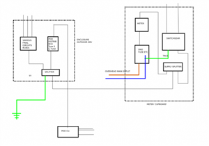
7b9cf34fb3da18dccd3044d711131e43-huge-ietwrforumspd1.png


(last para edited for clarity ... well that was the intention)
  • As far as I recall BS 7671 only demands type 1 SPDs where the building has lightning protection - but there does seem to be generally accepted industry advise that type 1 should also be used for overhead supplies. So I think it's a case of you pays your money and takes your choice on that one.


    I think you'll need SPDs in the TT part too. SPDs operate by shorting conductors together (e.g. L and PE) - so tend to raise the voltage on PE just as much as they reduce it on the L - indeed on a TN-C-S supply you might well find that the surge is pretty similar on both the L and PEN conductors in the first place so the SPD might have little to do. However take the live conductors into a TT area and you're almost back to square 1 again as the TT earth won't have have had the benefit of being 'pulled up' by the SPD in the TN installation. For instance, say we had a 10kV surge on the supply L - the TN SPD shorts L to PE so bringing L down to not much above 5kV and pulls the TN PE up to almost 5kV - the TN installation only sees the difference and so is happy, but the TT installation, with it's PE still at 0V sees 5kV between L and PE. (Or even worse case a 10kV surge is imposed on both the supply L and PE - TN SPDs have nothing to do, but the TT installation then sees the full 10kV).


    Generally there shouldn't be type 1 or 2 SPDs downstream of 30mA RCDs - both because the RCD is likely to nuisance trip if a surge occurs (if you're lucky) and (if you're unlucky) the RCD itself is damaged by the surge as it lacks upstream SPD protection. S-type (time delayed) RCDs can be upstream of type 2 SPDs - but often it's better to have CT2 wired SPDs before any RCDs - although a lot of care is needed to ensure that there's no possibility of a L-PE fault before the first tier of RCDs in a TT system.


       - Andy.
  • A couple of other points. A type 1 SPD won't necessarily protect electrical equipment - it's designed to temporarily equipotentially bond the supply to the LPS so there's no flashover and fire. So it's beefier but slower. So you'd need a type 2 in conjunction with it, and indeed some SPDs are sold as combo type 1 and 2's.


    Second, its generally recommended that a further SPD is added to DBs which are 10m or more downstream from the main SPD. This is due to a ringing effect which can double the transient voltage further down the wire. E.g. a 4kV spike on the supply is reduced to 1.5kV by the SPD at the main DB, but is 3kV by the time it reaches the second DB.
  • Ah right [with furrowed brow]. Therefore drawing on comments and just for further exploring the subject...


    In the example installation, if working with current switchgear, where would the type 2's be positioned ?   - Btw, I'm not asking for a design here, it's just exploring a learning curve for me?


    If a Type 1 is not necessarily needed, are there 'cascading/coordinated'  type 2's  to allow them to be put in at each consumer unit/db position (one of the house CUs is 25m away) and one at the origin ?


    On the TN-C-S side of things and if one of the consumer units is 20m or so from the intake position, then would it make sense to put type 2 in the CUs with nothing at the main intake (its outside and limited switchgear to sacrifice) connected up CT1 ?


    On the TT side, Type 2 connected CT2 infront of  the RCBO final circuit board and 100ma type s distrib (or perhaps a type 2 for each of those so some discrimination/selectivity perhaps ?), but then what would go in the POD consumer unit ?


    hmmm

    Habs

  • I am shifting tack a bit and any further comments would be appreciated please.


    Questions:


    1) is it possible for an earthy piece e.g. 3m tall metal lamp post(s),  on a TT'd installation part (fed from a main TN-C-S installation) to  bring a surge transient back inside the property ?


    2) if 1) is yes, where would the/a SPD go to protect from this ?


    3) as well as intending to protect equipment, are SPDs also protecting the conductor voltage rated insulation as well ?


    Thank you

    Habs


  • ... I think what I am trying to understand clearer is (as I chew this down, hopefully for food value): if there is consumer installation cabling outdoors, e.g. catenary, underground SWA, other connected metal work,  with a ground (or even cloud to cloud) strike, can that impart as a surge back up the line into other parts of the consumer installation   ?


    If that is the case, the way the outdoor service is supplied and where SPDs might go could be relevant ?


    Regards

    Habs
  • I think its reasonable to assume that earth connections entering a building (whether in the downstream or upstream direction) could briefly have a very high voltage induced on them relative to the live conductors in that building due to lightning, so you'd ideally want an SPD between line/cpc in both buildings at a point before that spike could reach sensitive equipment.


    An SPD is really about restricting spikes to the overvoltage category supported by the equipment it protects (see table 443.2). So this will include insulation (and test equipment!). So DBs, sockets, and the cabling and connectors between them are class III equipment, so should all be capable of handling 4kV spikes. So the SPD at the DB needs to reduce spikes to at least that. But if class II equipment like domestic appliances will be plugged in, then you need to be < 2.5kV at the sockets, and for electronic equipment (class I), then < 1.5kV at the socket.

  • the BS7671 advice on SPDs assumes wiring of the mains supply coming in as the source of the surge voltages.

    It is not really the correct advice for the external antenna situation, of which your external lamp post is a milder example. The problem is always to see which voltage is moving relative to what, and all the SPD can do is  become conductive enough to connect two things that were not connected before, at one point for the duration of the over-current.

    Unless the lamp post is taller than the surrounding building or on a very long feed, so it's 'earth' is a long way off the one for the house supplying it, I'd not worry. Yes some L-N-PE either at the post to protect the light fitting, or at the point the cable enters the house to protect the house may catch certain unlikely cases, but they are that, unlikley. 


    Where you really do have things you do need to protect, like tall antennas outside and an expensive listening station inside, then the incoming cables are shielded and all have metallic glanding to a common entry panel, and the idea is that high currents may flow in the armours and braids,  and may go in and out on the mains, or the telecomm cables or the antenna feeders, and all of these cables are kept at the same voltage so the equipment in the bunker is never 'doing the splits' between different voltages whatever happens outside.

    However, you are not working to those sort of Defstan or STANAG specifications, and do not need your installation to survive a small nuclear strike,  the requirements are a lot less onerous, and the cost/risk balance is very much in favour of cheaper.


    However, an outside light with a SWA feed back to the board and with the SWA armour earthed promptly to the MET is less likely to give trouble than one where the SWA is fed from another circuit indoors that also supplies a load of delicate stuff.

    In the same way if long external telcomms cables  call by the MET on their way in , rather than casually connect direct to some double insulated box of digital magic in the living room, the chances for that box surviving a thunderstorm are increased, as is the TV if the antenna braid is actually earthed to something.


    In the UK the protection of telephone lines at the customer end is not normally done, as the kit that would be damaged does not belong to the likes of BT Openreach anyway, so replacing it is free, to them, and lightning is quite rare here compared to many places.


    In places like Germany you will see things like  This little  box from Dehn  to catch the worst on the phone line as it comes in. Not common in the UK, and not normally an issue.


    Mike.

  • mapj1:

    In the UK the protection of telephone lines at the customer end is not normally done, as the kit that would be damaged does not belong to the likes of BT Openreach anyway, so replacing it is free, to them, and lightning is quite rare here compared to many places.


    In my mother's house, the old GPO junction box where the cable from the telephone pole comes inside and is terminated, also has a bare 4mm-ish cable running from it to the outside ground. Inside the box, this isn't connected to anything apart from a couple of lumps of brass separated by a few mm of plastic from the brass data terminals. I'd always assumed that this was acting as some sort of SPD??


  • GPO junction box where the cable from the telephone pole comes inside and is terminated, also has a bare 4mm-ish cable running from it to the outside ground. Inside the box, this isn't connected to anything apart from a couple of lumps of brass separated by a few mm of plastic from the brass data terminals. I'd always assumed that this was acting as some sort of SPD??


    Well in the GPO days, the phone was theirs, and so had some protection, though exactly what varied with the era and the part of the country  examples . My parents had the box with a sort of sprung fingers spark gap and a pair of series fuses.  When the VDSL man came he just looped past it, so it is now redundant.

    For at least 40 years (since the end of the earthed ringer party line wiring) the BT side of the UK phone network has not relied on a consumer side earth electrode.  This means common mode pulses where both lines flash up together relative to ground are not stopped from reaching the consumer side wiring. Until quite recently master sockets had a sealed gas filled spark gap (ceramic thing) between the A  and B lines (*), at least suppressing over sized differential signals but in the latest flavours that seems to have been optimised away too.

    Mike


    * A at 0V B at -50v when idle . When phone call in progress B comes up and A goes down an amount that depends on exchange distance and the loop current.

    To 'pick up' the phone must present 1kohm or less between A/B lines.

    According to SIN 352 the voltage across the phone will be up to 42 mA at 12.5 V (short line), up to 33.5 mA at 10 V, and will be not less than 25 mA at 9 V. (long line limit)

    Line reverses during calls if caller ID is in use.

  • I think the original BT "master socket" had a small SPD between the A & B lines. Nothing to Earth though.


    Many older phones lines did indeed have a local Earth connection - I was never sure if that was meant as a safety feature (ringing voltages are a little bit above the normal ELV range) and it's been dispensed with as modern phones don't have any exposed-conductive-parts, or whether it was part of the signalling system (there was both timed break and earth break recall - but I've only come across them with private branch exchanges, not ordinary BT lines).


       - Andy.