This discussion has been locked.
You can no longer post new replies to this discussion. If you have a question you can start a new discussion

SPD(s) for an outdoor TT install

Good morning


I am trying to get my head around surge protection - the *basic type and positioning* really- and taking an example situation please where surge protection may be added:


A moorland, overhead supplied, residential property; TN-C-S.


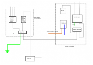
Outdoor regular wall meter cupboard in which is the DNO head, meter and some existing consumer switchgear (been as it is for over a decade with RCDs, MCBs from when the supply was TT) in an enclosure fed via a supply splitter block [henly] , which is there to supply two consumer units each at either end of the property.


Also fed from the splitter block, a supply to another nearby enclosure in which resides switch gear for TT outdoor services - lamp columns and electric gate 30ma RCBO final circuits and a  RCD type s distrib circuit to a 'garden work pod' which has a little sub-board.


(rough block diag attached to help description)


1) What would be the positioning and type of any surge protection  (where there is no LPS on the building rightly or wrongly)   ?


my questioning thoughts on this:

- near the origin (as in the source of energy) a  Type 1 as it is overhead fed, but not sure if CT1 or CT2 connection 

- in the consumer units a type 2  CT1 connected

- for the TT outdoor final circuits a type 2  , does this have to be upfront of RCBO being TT and  CT1 or CT2

- for the TT pod  distrib circuit, a type 2 and none  in the 'pod' sub board, or  none and type 2 in the pod subboard


- does the outdoor TT install even require SPD; can a 'surge' propogate back uptream into other parts

- future considerations, if alterations made e.g.


2) Lastly, is SPD simply about protecting connected equipment, or is it also about protecting  conductor insulation from voltages that might damage it ?


It does seem that adding type 1 SPD at the 'origin' (in meter box - other one is possible)  into this situation is nigh impossible without major works, so unless its possible to simply add it to each consumer unit/subboard as such... it seems academic, but still   it would be interesting to know where it should go ideally.


Regards

Habs


(perhaps one's ambition outweighs one's abilities)
7b9cf34fb3da18dccd3044d711131e43-huge-ietwrforumspd1.png


(last para edited for clarity ... well that was the intention)
Parents
  • GPO junction box where the cable from the telephone pole comes inside and is terminated, also has a bare 4mm-ish cable running from it to the outside ground. Inside the box, this isn't connected to anything apart from a couple of lumps of brass separated by a few mm of plastic from the brass data terminals. I'd always assumed that this was acting as some sort of SPD??


    Well in the GPO days, the phone was theirs, and so had some protection, though exactly what varied with the era and the part of the country  examples . My parents had the box with a sort of sprung fingers spark gap and a pair of series fuses.  When the VDSL man came he just looped past it, so it is now redundant.

    For at least 40 years (since the end of the earthed ringer party line wiring) the BT side of the UK phone network has not relied on a consumer side earth electrode.  This means common mode pulses where both lines flash up together relative to ground are not stopped from reaching the consumer side wiring. Until quite recently master sockets had a sealed gas filled spark gap (ceramic thing) between the A  and B lines (*), at least suppressing over sized differential signals but in the latest flavours that seems to have been optimised away too.

    Mike


    * A at 0V B at -50v when idle . When phone call in progress B comes up and A goes down an amount that depends on exchange distance and the loop current.

    To 'pick up' the phone must present 1kohm or less between A/B lines.

    According to SIN 352 the voltage across the phone will be up to 42 mA at 12.5 V (short line), up to 33.5 mA at 10 V, and will be not less than 25 mA at 9 V. (long line limit)

    Line reverses during calls if caller ID is in use.

Reply
  • GPO junction box where the cable from the telephone pole comes inside and is terminated, also has a bare 4mm-ish cable running from it to the outside ground. Inside the box, this isn't connected to anything apart from a couple of lumps of brass separated by a few mm of plastic from the brass data terminals. I'd always assumed that this was acting as some sort of SPD??


    Well in the GPO days, the phone was theirs, and so had some protection, though exactly what varied with the era and the part of the country  examples . My parents had the box with a sort of sprung fingers spark gap and a pair of series fuses.  When the VDSL man came he just looped past it, so it is now redundant.

    For at least 40 years (since the end of the earthed ringer party line wiring) the BT side of the UK phone network has not relied on a consumer side earth electrode.  This means common mode pulses where both lines flash up together relative to ground are not stopped from reaching the consumer side wiring. Until quite recently master sockets had a sealed gas filled spark gap (ceramic thing) between the A  and B lines (*), at least suppressing over sized differential signals but in the latest flavours that seems to have been optimised away too.

    Mike


    * A at 0V B at -50v when idle . When phone call in progress B comes up and A goes down an amount that depends on exchange distance and the loop current.

    To 'pick up' the phone must present 1kohm or less between A/B lines.

    According to SIN 352 the voltage across the phone will be up to 42 mA at 12.5 V (short line), up to 33.5 mA at 10 V, and will be not less than 25 mA at 9 V. (long line limit)

    Line reverses during calls if caller ID is in use.

Children
No Data