Alan Capon:
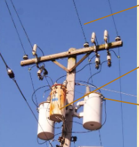
Broadgage is the closest with the first part of his post. What you are describing is a six winding zigzag transformer, connected across the three LV phases and neutral. If the phase to neutral voltages are out of balance, it will draw current from the higher voltage phases, transferring the power to the lower voltage phase, to equalise all three phase to neutral voltages.
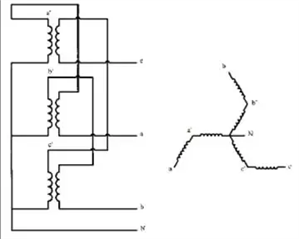
Using Mike’s first sketch, and assuming two windings per pole (or limb) of the transformer. If you call the windings R1, R2, Y1, Y2, B1 and B2, the connections between the phase connections and Neutral would be:
Red Phase R1 -Y2 Neutral
Yellow Phase Y1 -B2 Neutral
Blue Phase B1 -R2 Neutral.
I have used the minus sign to denote the second winding is connected anti-phase, such that it subtracts from the vector sum.
it is usual practice to place a fuse between the neutral of the balancer and the system neutral - if you lose a phase, perhaps through a blown fuse, it will present a near short on the remaining two phases, attempting to equalise the voltages, taking the remaining two fuses. I can’t do the maths from first principles anymore. When I catch up with the text book on my office desk, I will post some more information.
I suspect my explanation is “clear as mud”. I find it difficult to explain through a text interface!
Regards,
Alan.
I know about using a zig-zag transformer to derive a neutral/earth reference when a transformer winding doesnt have a star point (eg. a delta winding) but I'd never thought about connecting it to an existing system neutral in order to allow zero sequence currents to flow and equalise the voltages.
The HV neutral isn't normally distributed, so this must be for use on the LV network?
We're about to take you to the IET registration website. Don't worry though, you'll be sent straight back to the community after completing the registration.
Continue to the IET registration site


