Can some one please explaine to me if possible how a static balancer works? I've seen a couple of these things installed at the end of long LV distributors but never been able to find how they work as far as I can tell they are just 3 windings connected in star but I've got no clue how they balance voltage.
It is not 3 separate windings magnetically. It is one core with 3 legs and windings on each leg
(and all our normal 3 phase transformers are like this, so to a degree automatically balance, unlike the US where they put 3 single phase devices on a pole and call it a 'phase bank' )
EDIT
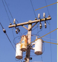
Sidetrack into American practice..
They do not even seem to have used 3 transformers from the same batch in this example, so here the 3 phases will never balance well at any load level.
So back to that 3 limbed core, when one winding is magnetised, the magnetic field returns via the other two limbs of the core, inducing a voltage in those windings if it is not already there that must sum, transformer-like to the same voltage. (much as if there were only 2 limbs so it was more like a squared- off toroid the magnetism would be the same all round, and we'd not be surprised to see the same volts/turn on both sides ).
This is a bit simplified, but is the basic concept.
EDIT
(Here is a very nice if quite slow colour animation of all the little magnetic domains in the cores swinging round as full cycle of 3 phase passes. Note how each leg energises the flux lines it creates loop round by the other 2 legs in a mixture that changes over time. )
So, I hope it is now also obvious why this does not work as well,and why 3 phase transformers are not made this way..
It is not 3 separate windings magnetically. It is one core with 3 legs and windings on each leg
(and all our normal 3 phase transformers are like this, so to a degree automatically balance, unlike the US where they put 3 single phase devices on a pole and call it a 'phase bank' )
EDIT
Sidetrack into American practice..
They do not even seem to have used 3 transformers from the same batch in this example, so here the 3 phases will never balance well at any load level.
So back to that 3 limbed core, when one winding is magnetised, the magnetic field returns via the other two limbs of the core, inducing a voltage in those windings if it is not already there that must sum, transformer-like to the same voltage. (much as if there were only 2 limbs so it was more like a squared- off toroid the magnetism would be the same all round, and we'd not be surprised to see the same volts/turn on both sides ).
This is a bit simplified, but is the basic concept.
EDIT
(Here is a very nice if quite slow colour animation of all the little magnetic domains in the cores swinging round as full cycle of 3 phase passes. Note how each leg energises the flux lines it creates loop round by the other 2 legs in a mixture that changes over time. )
So, I hope it is now also obvious why this does not work as well,and why 3 phase transformers are not made this way..

