This discussion has been locked.
You can no longer post new replies to this discussion. If you have a question you can start a new discussion

Using BS8436 cable - Thinking check

Good morning everyone, its that time again where if you could spare five minutes of your expertise I would be much obliged!

I currently have to install cabling and controls for a new retrofit underfloor heating system. This system is low profile and involves the pipework laid on a (appx 20mm deep) mat. The existing floor construction is concrete. All pipework will then be set in a deep base levelling compound prior to full tiling of the floor.

The house is fully decorated and the client is unwilling to disturb decoration unless absolutely necessary. It has been suggested to remove coving and run cabling behind to thermostats but this has met firm opposition. There is no access from above other than this.

My current thinking - and it is this that I would appreciate your input on/abuse if you think it's unacceptable :)…

To install 1.5mm BS8436 cable within 16mm flexible conduit in screed where necessary and otherwise behind skirting boards which are being replaced in the course of works. Where in floor (in my created building void) the conduit will be 100mm away from the central heating loops but would inevitably be within the thermal mass of the floor. It will be installed away from where any future installation of carpet would necessitate gripper rods to be nailed down as far as practicable.

Conservatively I have calculated the following derating factors which I hope will be more than conservative enough to make sure Iz is within tolerance for my protective device.

Table 4D2A 1.5mm2 Cable Reference Method A (worst case scenario conservatively selected as more likely to be reference method b). Four core cable rating (three phase (again going conservative to allow for the switch line). Current carrying capacity: 13 Amps At an ambient temperature of 30 degrees

13 x 0.50 = 6.5 amps  (derating for a 60 degree ambient temp even though specification says 45-50 degrees for the heating loop water temperature and the ambient temperature of the floor where the cables will be will almost certainly be far below this as they will not be up against them.

6.5 x 0.79 = 5.135  (derating for three grouped cables. Highly unlikely to be necessary (but just in case). These cables are for thermostats only so are almost certainly going to be carrying less than ⅓ grouped current rating.

5.135 x 0.65 = 3.33 amps (additional (bonus) derating for unventilated cabling system as per notes [2 layers of cable - unventilated]

I'm going to use a 3A type B MCB (class 3) at the manifold which will probably also act as the isolator for the central heating controls. 

Other than being super cautious can you guys see any wrong-think in my workings - would there be anything else you would consider?

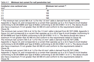
This is the first time I've used BS8436 cable and primarily it is being used to get around the cable not being in permitted zones/at depth within the floor and walls. I've read the guidance with regard to using type B class 3 MCB's at a fault current <5kA which is what will be happening in this installation. I have noticed some suppliers give a maximum energy let through for the protective device (42000A2S) but annoyingly the particular supplier (Atom) that make the cable I have been given do not - I've asked them but am not holding my breath. Do you know whether this maximum energy let through is built into the product standard by any chance. The energy let through of the 3A type B MCB (and probably the 16A type B at the origin of the circuit) is almost certainly going to be far below 42000A2S within an installation with a PEFC <3kA - do I need to look any further into this or is the use of type B MCB's just a ‘given’ with this type of cable.

Hopefully you haven't all nodded off during that. Thanks in advance for any help and advice you can give.


  • Hi Mike, thanks, for sure I do appreciate that the risk is small and possibly concerned with events beyond my reasonable control. I do find it comforting knowing that it was ok when you left it at least though! Particularly when as noted you're contemplating an installation that, although compliant, is a bit beyond the ordinary!

    Regarding the PFC thing- when I come across reduced size ring final CPC's I do check the energy let through of the CPD's at onsite measured PEFC and compare this to the K2S2 of the CPC in an attempt to prove compliance. I also do this when I encounter higher pfc's on installations with T&E present. Would you consider that a redundant exercise given the discussed feasibility of network change? 

    The same I suppose would apply to your measured earth fault loop readings on circuits if they were a bit on the edge. I've always based it on how it tests on the day particularly with existing installations. I've seen the design guide recommends designing for worst case scenarios from the network. i.e. a 16kA pfc and for example a 0.8 ohm ze for a tns system. In the real world this just isn't going to be practical though is it - and T&E would never be seen again - even in a domestic environment as >3kA some of the cpc sizes get a bit skinny (as table b7 in the onsite guide recognises).


    Going back to the type c/rcbo thing - it seems to be a widely held misconception:


    Seriously though. Thanks so much to you both for the discussion. It's great to be able to bounce these things off someone!


  • I think it is good you are being thorough, many in your shoes would not bother to be.

    But, do realize  you are starting to worry about a small effect - by all means note the PSSC while you have your meters out, but the whole “what is the the exact  fault current?”  thing  is not that black and white - tomorrow the street cable may be upgraded to make way for some EV chargers, or on the other hand the house holders may use  larger or smaller nail than the one in the BSI test. Or,  most likely, it will never get nailed, ever, in the life of the building.

    And, if it does trip someone could just keep re-setting the breakers till it burns clear, or they may realize their error and remove the nail and yet may or may not get the cable repaired.

    You cannot protect against all possible events however unlikely, just the reasonably credible ones.

    And yes, thinking of the area engineer, not everyone with an official role talks sense all of the time. Some of us more than others , so let's hope it was a bad day, and not a fundamental mis-understanding about what is in an RCD.

    Mike.

  • Thanks both. Atom have sent through clause 12 of the British Standard which seems to confirm all discussion here i.e. to safely protect the cable the mcb needs to have a maximum energy let through <42000 A2S and the circuit breaker should be type b, class 3, 60898 of correct value etc. Makes me feel a bit better anyway that I understand what I'm installing! As ever thanks for all your help.

    Is it legitimate to confirm the max energy let through of the device is <42000 A2S for the measured fault current of the installation or do you think this should be verified as a generic figure from the manufacturer?

    Interestingly enough I've always tried to swerve Type C's with T&E as I have noticed that the energy let through can be a bit tight for a near origin fault and sometimes even exceeds the CPC K2S2 at even modest fault levels - particularly with 1mm. But as you say…. seems to get a launched in at a rate of knots everywhere and no one seems too worried. Then again there were a lot of people on the Titanic and it still sank. I think I had an NICEIC area engineer actively encouraging it once on the basis that the 30mA RCD element of an RCBO would restrict the fault current to 30mA (which it wouldnt). 


  • Where did you obtain the information about the K2S2 of the foil being generally greater than that of a 1mm copper cpc Andy? 

    Basically BS 8436 cable manufacturer's data - most of which seem to suggest that same sort of figures - 42,000 A²s for 1.0mm² or 1.5mm² cable and 60,000 A²s when used with 2.5mm² or 4.0mm² cable - compared with the normal calculation that gives 13,225 A²s for 1.0mm² c.p.c. in T&E and 29,756 A²s for a 1.5mm² - which suggest to me that BS 8436 cable is hugely superior to T&E in terms of withstand.

    Yet there's all this fuss about only using certain values of B-type MCBs with BS 8436 cable while at the same time we stick 1.0mm² c.p.c. T&E on a C16 or 1.5mm² c.p.c. on a B32 in a 6kA or even 16kA situation without a second thought.

    Probably we should be looking more closely at the T&E situation, but my general feeling is that if you'd be happy using T&E in a particular situation then using BS 8436 cable instead can only be an improvement.

       - Andy.

  • Thanks Mike, that makes sense and I'm starting to think I might be seriously in danger of overthinking this. 

    Do you think I am reading/complying with the british standards correctly if I were to use the MK Type B MCB which at 6kA (its maximum fault current rating) has a maximum energy let through of approximately 13000A2S which is significantly less than the stated maximum for the protective device of 42000A2S and that the cable would be capable of fulfilling its purpose in the event of a ‘penetration event’.

    82a79b6f47709141168074630c42e5ae-original-image.png

    In reality both the fault current and the energy let through will be far lower than this. As I said previously I'm anticipating a PEFC <3kA at origin. The start of the 8436 cabling and 3A device will be remote from the origin as well again bringing down the fault current.

    I will be complying with the ECA guidance as well i.e. ensuring use of type b devices and only when pfc is <5kA.

    Is there anything I'm missing here or have I got the right end of the stick?

    Thanks again for all your help all. It's always good fun trying something new. :)

  • The MCB let-through in I2t == joules per ohm is the maximum, over the full range of prospective fault currents that are between the onset of near instant tripping (5 times In for a B type then) and the upper limit of 6000A or whatever is stamped on the breaker.

    This does cover all cases. rest easy. The energy  in joules it takes to vaporise a fixed amount of  however much aluminium, is more or less independent of the rate of arrival of those joules, once you are fast enough to be able to consider the process adiabatic.


    That was 160 amps for a second - so perhaps for a 10th of a second 450 amps (times by root 10)

    for 1/100 of a second, more like 1.6kA (times by root 100)

    for 1/1000 second, more like 4.5kA  (times by root  1000)

    etc. All give the same heating power into the metal so the same degree of damage.

    Mike.

  • All the gear is onsite. It's my problem now! :)

  • Thanks both. In fairness Atom did come back to me just with an excerpt from the British Standard which mentions using a CPD with an energy let through <42000A2S.

    c85f9773879875233aab6dee78819c13-original-image.png

    I have seen this figure quoted in other manufacturers literature as well. I have the energy let through data for a B6 MK Sentry (they make a 3A type b as well) which puts the energy let through at 3kA at around 10000A2S which as you said Andy would be fine for a 1mm CPC. What is turning me about a little bit is that the test procedure doesn't seem to make an allowance for a low impedance/high fault current short. Im just struggling as to how I as the designer can ensure fault protection at all points in the circuit or will I have achieved this by virtue of meeting disconnection times and following the british standard? It would seem impractical to use this cable if it can only protect against a short to a maximum current of 100/160 amps!

    It makes sense the consideration that we're not necessarily protecting the pvc insulation but rather ensuring that the circuit can disconnect and I suppose at the point in time the cable gets pinned it is knackered but yes the thought of the foil frying post penetration and then the circuit being re-energised is not a comforting one. 

    Where did you obtain the information about the K2S2 of the foil being generally greater than that of a 1mm copper cpc Andy? I'd be happy my 3A MCB would take care of any drama if this were the case :)


    Thanks again chaps.


  • Scrambled: 
     

    It has been suggested to remove coving and run cabling behind to thermostats but this has met firm opposition. There is no access from above other than this.


    Battery operated wireless thermostats?

  • As a quick sanity check, the allowable energy let-through for 1.0mm² c.p.c. in a T&E cable would be k²S² - or usually 115² x 1² = 13,225A²s.  The withstand for the aluminium foil in a BS 8436 cable is likely to be significantly higher than that (especially as in this case, as Mike notes, we're worried temperatures that will melt/vapourise the aluminium rather than just permanently damage PVC insulation).

        - Andy.