
Evening all. As ever I'm wrestling with a conundrum that I've hit a bit of a brick wall with. I could use a few pointers as to what I am missing/fill in some blanks.
Sizing of protective conductors:
If we take say a circuit wired in 1mm cable, protected by a suitable device, lets say a Type C 6A 60898. By selection from 54.7 we can use a 1mm cpc. From the design guide it is stated that if the current carrying capacity of the protective conductor is the same as the line conductor then the adiabatic equation will be satisfied (so long as the circuit has been designed for protection against overload) but if it is of reduced current capacity then we have to either select (54.7) or calculate (adiabatic/verify energy let through) to check the conductor is suitably protected. As a 1mm cpc is the same as the line conductor apparently no issues...
But...
Table B7 of the onsite guide states that the minimum CPC size for a class 3 energy limiting device Type C 16A or less, at a sub 3kA fault level is 1.5mm2. Presumably because the A2S according to BSEN60898 is permitted to exceed the K2S2 of a 1mm conductor for this device. I've checked through a number of manufacturers energy let through charts and indeed for a 6A Type C breaker at certain fault current levels (some around 2.0kA) - the I2T does exceed the 13225 K2S2 for a 1mm conductor. Surely though this would apply to a line-neutral fault as well?
So...
Why is it ok that potentially I could have a conductor with a K2S2 less than the I2T of the protective device in the case of a 1mm2/1mm2 cable just because it has been selected rather than calculated?
Furthermore... if that is truly ok - why (if fault current levels are at the aforementioned) does that 1mm conductor potentially become unsuitable if it is partnered with a 1.5mm2 line conductor instead?
I have a suspicion that the impedance/resistance of the line conductor (being the same size) is coming into play here and this will be the difference effecting the thermal stress on the protective conductor. But I could do with a bigger brain to point me in the right direction!
I hope that made sense! Thanks as ever for tolerating my questions!


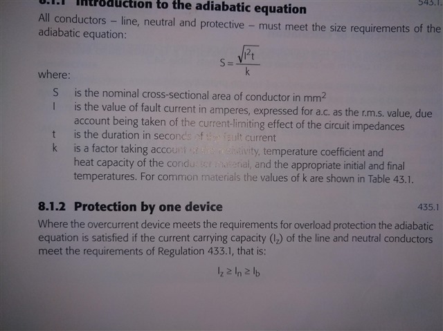 Apologies for the confusion Graham thanks for coming back to me. I'm familiar with the difference between overload and fault. When I referenced the overload consideration I was referring to this in the design guide.
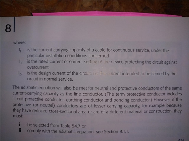 followed by this... which seems to suggest that if the overcurrent protective device is ok for overload protection to a conductor correctly coordinated with the Iz of the conductor then the adiabatic equation will be satisfied for fault protection... which then takes me back to my original question of how that could be in the example if the fault current level were at a point where the K2S2 was less than the I2T of the device... because by selection it would all appear suitable unless the 1mm conductor happened to be the cpc of a 1.5mm cable. Hopefully that's a bit clearer!