This discussion is locked.
You cannot post a reply to this discussion. If you have a question start a new discussion

Sizing of protective conductors - what am I missing here

Evening all. As ever I'm wrestling with a conundrum that I've hit a bit of a brick wall with. I could use a few pointers as to what I am missing/fill in some blanks.

Sizing of protective conductors:

If we take say a circuit wired in 1mm cable, protected by a suitable device, lets say a Type C 6A 60898. By selection from 54.7 we can use a 1mm cpc. From the design guide it is stated that if the current carrying capacity of the protective conductor is the same as the line conductor then the adiabatic equation will be satisfied (so long as the circuit has been designed for protection against overload) but if it is of reduced current capacity then we have to either select (54.7) or calculate (adiabatic/verify energy let through) to check the conductor is suitably protected. As a 1mm cpc is the same as the line conductor apparently no issues...

But...

Table B7 of the onsite guide states that the minimum CPC size for a class 3 energy limiting device Type C 16A or less, at a sub 3kA fault level is 1.5mm2. Presumably because the A2S according to BSEN60898 is permitted to exceed the K2S2 of a 1mm conductor for this device. I've checked through a number of manufacturers energy let through charts and indeed for a 6A Type C breaker at certain fault current levels (some around 2.0kA) - the I2T does exceed the 13225 K2S2 for a 1mm conductor. Surely though this would apply to a line-neutral fault as well?

So...

Why is it ok that potentially I could have a conductor with a K2S2 less than the I2T of the protective device in the case of a 1mm2/1mm2 cable just because it has been selected rather than calculated?

Furthermore... if that is truly ok - why (if fault current levels are at the aforementioned) does that 1mm conductor potentially become unsuitable if it is partnered with a 1.5mm2 line conductor instead?

I have a suspicion that the impedance/resistance of the line conductor (being the same size) is coming into play here and this will be the difference effecting the thermal stress on the protective conductor. But I could do with a bigger brain to point me in the right direction!

I hope that made sense! Thanks as ever for tolerating my questions!

  • Why is it ok that potentially I could have a conductor with a K2S2 less than the I2T of the protective device in the case of a 1mm2/1mm2 cable just because it has been selected rather than calculated?

    You can't ... for both L-N and L-E faults, the cable must be protected by the protective device.

    I think you may be confusing the differentiation within "overcurrent protection" between "overload" and "fault current" protection ? Both sets of requirements must be satisfied.

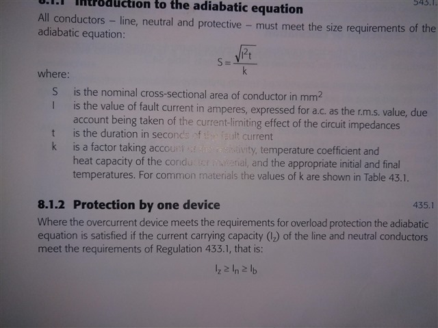
  •  Apologies for the confusion Graham thanks for coming back to me. I'm familiar with the difference between overload and fault. When I referenced the overload consideration I was referring to this in the design guide.
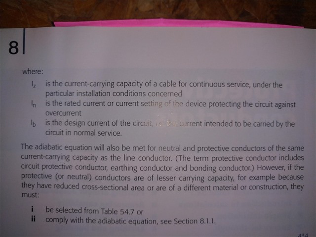
  •  followed by this... which seems to suggest that if the overcurrent protective device is ok for overload protection to a conductor correctly coordinated with the Iz of the conductor then the adiabatic equation will be satisfied for fault protection... which then takes me back to my original question of how that could be in the example if the fault current level were at a point where the K2S2 was less than the I2T of the device... because by selection it would all appear suitable unless the 1mm conductor happened to be the cpc of a 1.5mm cable. Hopefully that's a bit clearer!

  • This situation can be a bit tricky, and whilst the design guide is quite correct in what it says the real outcomes of faults may not be that which you expect. The real problem is that faults are not discussed as "credible faults". The situation you have described can happen on much larger cables too, typically on the connections to large transformers where potential fault currents may be very high, typically 100kA at the transformer terminals. It is particularly difficult when several cables are used in parallel, as only one of them will be subject to the fault (Earth) current.

    Is it credible that a T&E cable becomes faulty, but not damaged within a short distance of the circuit breaker? Once you have a metre of 1mm2 cable the potential fault current has fallen to a much lower level, and your cable is safe. If it does develop a short circuit or Earth fault close to the breaker then it will need to be replaced anyway, so some overtemperature damage is acceptable. As you have noticed the k2s2 may be exceeded at some small range of fault current but not elsewhere, what is the effect of this? It is simply that the conductor temperature will rise somewhat more than the normal limits during the fault. The position of this fault on the cable can be calculated and may be very short but how realistic is this calculation? How many assumptions have you made about PSCC, fault resistance (zero?), and ambient temperature.

    I know that many people will argue with my point, but it is the difference between reality and theory. The number of circuits that any experienced person has ever seen with the scenario after a fault you are discussing is probably zero, simply because it doesn't happen, although it is possible. The figures you are using are all "worst possible case", the I2t, the cable temperature, almost zero length, the artificial temperature limit for the Earth conductor (chosen to remove any possibility of fire) etc.

    If you analyze the zero-length fault cable sizes for many installations you will find that there are non-compliances, but short circuits inside distribution boards are very unusual, probably unknown unless mechanical damage has occurred. Loose connections are much more common and may lead to fires because the heat is sustained and may be very high, red hot terminals are quite common.

  • Ah, I see now where you are coming from.

    I will have to think carefully about this, but my initial thought that there is a qualification which may be missing from Section 8.1.2 in EIDG, which is present in the regulation it refers to.

    The reality is that, Regulation 435.1 requires you to check adiabatic (Regulation 434.5.2) for the live conductors, regardless of whether they are protected for overload, and if you've already done that, a cpc of the same size is already protected.

    435.1 Protection afforded by one device
    A protective device providing protection against both overload current and fault current shall fulfil the requirements of the relevant regulations in Sections 433 and 434.

    Except as required by Regulation 434.4 or 434.5.2, where an overload protective device complying with Regulation 433.1 is to provide fault current protection and has a rated short-circuit breaking capacity not less than the value of the maximum prospective fault current at its point of installation, it may be assumed that the requirements of this section are satisfied as regards fault current protection of the conductors on the load side of that point.

    The validity of the assumption shall be checked, where there is doubt, for conductors in parallel and for certain types of circuit-breaker e.g. non-current-limiting types.


    So I think you are correct, it doesn't make sense, and it's not simply the case that conductors are protected against fault current just because the protective device protects them against overload current, and this is particularly true of circuit-breakers because of the transition between thermal and magnetic characteristic, or with non-current-limiting circuit-breakers.

    ... I will come back to this thread to confirm.

  • Thanks Graham. Having followed through those regulations it makes perfect sense as far as BS7671 goes... ie. that as you originally said the i2t can't exceed the k2s2 - so that does solve the discrepancy in my head regarding what is commonly taught practice and indeed the design guide is saying. Just checked the most up to date design guide and again under fault protection the same statement is made with no visible qualification to it.

    David whilst I appreciate we might be talking about an unlikely event - nonetheless BS7671 doesn't really permit us to make that decision as far as I can tell for a circuit unless we can call into effect 434.3 which might be a bit of an ask in terms of general compliance when designing a circuit. I appreciate that there is the real world and BS7671 land but even so.... Even as a hypothetical it's nice to clarify! Thanks anyway!

  • Just checked the most up to date design guide and again under fault protection the same statement is made with no visible qualification to it

    Thank you. I have already fed this discussion back, so if any clarification is required, it can be added.

  • Why is it ok that potentially I could have a conductor with a K2S2 less than the I2T of the protective device in the case of a 1mm2/1mm2 cable just because it has been selected rather than calculated?

    I'm with you on this one - there's certainly something that doesn't stack up (and we've discussed this in the past). Similar situations can appear using a 1.5mm² c.p.c. on a ring with a B32 protective device where fault currents might be large-ish.

    I suspect it's mostly historical accident - the UK has a long history of both ring final circuits and reduced c.p.c.s and/or small (6A) lighting circuits which conspire to mean relatively small conductors and relatively high capacity single phase supplies so potentially high fault currents (up to 16kA on paper). Whereas EN standard MCB specifications seem to have been were dreamt up with more European situations in mind (low fault currents in domestics, no rings, full size c.p.s.c on small circuits, min 1.5mm² conductor size). Yet UK practice continued and not much harm appeared to occur.

    There was an attempt a while back to make the minimum conductor size 1.5mm² rather than 1.0mm² - which would help avoid some of these problems (and similarly align with continental practice) but was pretty much defeated by UK custom and practice (there had to be an exception for "lighting circuits").

    So much guidance (e.g. the OSG) is rather caught between a rock and a hard place - BS 7671 says what needs to be achieved, but that's neigh on impossible using BS EN circuit breakers and the small cables we're used to. There have been valiant attempts - using favourable manufacturer's data rather than generic values from BS EN 60898, and using the actual fault current rather than the rated breaking capacity of the MCB, but it's all still a bit of a kludge to my mind.

    Such thing were much simpler with fuses - as their energy let-though doesn't significantly increase with increasing fault currents, unlike MCBs, It was safe to assume that if the device provided overload protection and it had suitable breaking capacity, then it would naturally provide fault protection (to the conductors).

       - Andy.

  • Further to Andy's comments above /below sideways in this forums odd format.. 

    It all hinges on the fact that as fault currents rise, fuses and cable damage, both being essentially thermal, both get faster more or less pro-rata together.

    The rather unhelpful unit of amps squared seconds can also be considered to be units of joules per ohm, and maybe that makes it more intuitive what is happening  during the instant of flash crackle and pop - each ohm ( more likely small fraction of an ohm for real cables ) of metal in the fault path gets heated by that many joules, but the volume of metal to absorb those joules determines how hot it will get. (less metal volume or more joules, then it is pro-rata hotter...)

    For a fuse once you get into the fast part of the blowing curve, at least until onset of catastrophic rupture, the joules per ohm are more or less constant, and set by the no of joules to melt the (resistive )fuse element.

    A breaker on the other hand cannot get much faster than supersonically parting  contacts, as the arc has to be in free air - in an HR fuse it is normally in sand, which breaks it up as it forms.

    But we are not anywhere near burning a 1mm CPC open circuit with a 16A breaker on a 16kA  PSSC - though the PVC around it will look very unhappy afterwards.

    But as others have noted,  1m down the 1mm cable is 30-40 milliohms of extra fault loop assuming L and E are both 1mm2, so our PSSC starts to fall back from that theoretical 16kA quite fast . (1kA is 230millohms, 10kA is 23 milliohms, so 1m of 1mm  T and E limits you to about 6-8kA on a really bad day, even if the origin PSSC was infinite, and it never is. ( - and that is even if you can manage a silver nail lossless fault, and I bet you can't, a truly lossless fault has no flash and is silent, real ones go bang and do some mechanical work as well)

    Now I suppose you could turn a screw into the lighting cable as you fixed the consumer unit to the wall, so the cable is a few inches long, but that is about the only way you will see the full  fault current. - and if you did, then the fact that cable insulation gets singed is a 'so what ?' you'd  strip back and replace at least the last foot or so  anyway.

    Mike.

  • Thanks all. As ever it's been very helpful. Hope you've all had a nice weekend!