This discussion is locked.
You cannot post a reply to this discussion. If you have a question start a new discussion

Open PEN detection for 722.411.4.1 (iv)

Following on from the recent discussion about the adequacy of open-PEN detection devices that disconnect when the L-N voltage goes outside of the 207-253V range and how, when the single phase installation is fed from a 3-phase supply system, some open-PEN situations might go unnoticed even though the PEN/PE voltage can be significantly higher than 70V from true Earth.

Can people check that I'm understanding this correctly please?

As I see it, once the PEN becomes disconnected, it's free to float from Earth and can therefore be dragged towards the various L1/L2/L3 voltages depending on any impedances left between the severed N and the line conductors (usually any connected loads).

So thinking about it in phasor diagram terms, you have the usual triangle formed by L1/L2/L3 and N can then be dragged to any position within that triangle.

The detection device is looking at L-N voltages - or to put it another way, it's measuring the voltage on the N by using L as a reference. It's only seeing one phase, so can't work out anything about phase angles so it measures the magnitude of the voltage difference only - the phase angle of the measured L-N voltage could be anything. So I'm thinking that any given voltage different like that would show up on a phasor diagram as an arc (or circle) centred on the L position (L1 say) - the radius represent the magnitude of the voltage difference from L and the angle could be anything (within limits) - hence an arc rather than a single point.

So drawing arcs for the 207V and 253V from L, I get a region in between where the open-PEN device will think all is well.

So I've got this:
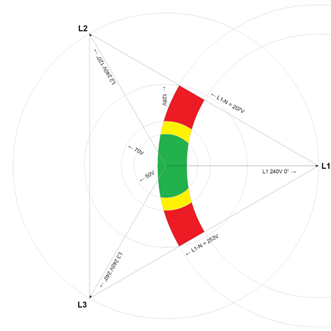
so the coloured regions are were the device thinks all is well - green where the N/PE voltage is actually ≤50V from true Earth, yellow between 50V and 70V (usually deemed acceptable for EV situations) and red where the device thinks all is well but the N/PE voltage is actually in excess of 70V from true Earth (anything up to 128V in this particular example). For the remaining unshaded areas of the triangle, the device will see L-N out of range and disconnect. Does that all make sense?

I've had to make an assumption about the actual line voltage present - since the N/PEN voltage is measured against that - I picked 240V as being typical for a UK installation, but of course it could vary considerably - which I suspect will mean that there could be an even wider range of PEN voltages that under particular circumstances the device would regard as being acceptable.

   - Andy.

Parents
  • The IET states that an open pen detection device should only be used on a single phase installation, but many three phase car chargers are now not requiring an earth rod. I'm assuming they have a three-phase Pen fault device onboard. Is that right? has something changed that I'm unaware of?

  • but many three phase car chargers are now not requiring an earth rod.

    What type of 'three-phase car charger' are you talking about? Mode 3, Mode 4?

    I'm assuming they have a three-phase Pen fault device onboard. Is that right?

    Never assume. There are a number of issues at play here, and it might not be a simple answer to your question. In addition, if the charging equipment is manufactured for the global market, the manufacturer's installation advice may not be UK specific (and/or may not comply with BS 7671).

    In some Mode 4 charging points, the output may well be configured as an IT system, and the manufacturer may be recommending some form of means of earthing for the IT system. In some installations, it will be safer to connect this to the installation's means of earthing - in other circumstances, or where there is no open-PEN detection and there is a PME supply, a separated earthing system is necessary, but this should follow the same rules as separating TT where that is used.

    The requisite guidance on all of this is in the IET Code of Practice for Electric Vehicle Charging Equipment Installations, 4th Edition.

Reply
  • but many three phase car chargers are now not requiring an earth rod.

    What type of 'three-phase car charger' are you talking about? Mode 3, Mode 4?

    I'm assuming they have a three-phase Pen fault device onboard. Is that right?

    Never assume. There are a number of issues at play here, and it might not be a simple answer to your question. In addition, if the charging equipment is manufactured for the global market, the manufacturer's installation advice may not be UK specific (and/or may not comply with BS 7671).

    In some Mode 4 charging points, the output may well be configured as an IT system, and the manufacturer may be recommending some form of means of earthing for the IT system. In some installations, it will be safer to connect this to the installation's means of earthing - in other circumstances, or where there is no open-PEN detection and there is a PME supply, a separated earthing system is necessary, but this should follow the same rules as separating TT where that is used.

    The requisite guidance on all of this is in the IET Code of Practice for Electric Vehicle Charging Equipment Installations, 4th Edition.

Children
  • Its a mode 3 AC 22kw. The Rolec Data sheets state a PEN fault device and no Earth rod is needed. But this is where I'm confused because bs7671 722.411.4.1(iv) states pen protection can only be used on a single phase device (according to the IET Electric vehicle charging equipment installation online course, I must admit I currently hold the blue 18th addition and that reg is not in there so assuming its in the latest book which I will pick up soon.

  • Under BS 7671:2018+A1:2020, there are two more options for PEN fault detection, that don't have the word "single phase", that is 722.411.4.1 (iii) and 722.411.4.1 (v).

    In BS 7671:2018+A2:2022, the words "in a single-phase installation" have been removed from 722.411.4.1 (iv).

  • thankyou for claifying