This discussion is locked.
You cannot post a reply to this discussion. If you have a question start a new discussion

Open PEN detection for 722.411.4.1 (iv)

Following on from the recent discussion about the adequacy of open-PEN detection devices that disconnect when the L-N voltage goes outside of the 207-253V range and how, when the single phase installation is fed from a 3-phase supply system, some open-PEN situations might go unnoticed even though the PEN/PE voltage can be significantly higher than 70V from true Earth.

Can people check that I'm understanding this correctly please?

As I see it, once the PEN becomes disconnected, it's free to float from Earth and can therefore be dragged towards the various L1/L2/L3 voltages depending on any impedances left between the severed N and the line conductors (usually any connected loads).

So thinking about it in phasor diagram terms, you have the usual triangle formed by L1/L2/L3 and N can then be dragged to any position within that triangle.

The detection device is looking at L-N voltages - or to put it another way, it's measuring the voltage on the N by using L as a reference. It's only seeing one phase, so can't work out anything about phase angles so it measures the magnitude of the voltage difference only - the phase angle of the measured L-N voltage could be anything. So I'm thinking that any given voltage different like that would show up on a phasor diagram as an arc (or circle) centred on the L position (L1 say) - the radius represent the magnitude of the voltage difference from L and the angle could be anything (within limits) - hence an arc rather than a single point.

So drawing arcs for the 207V and 253V from L, I get a region in between where the open-PEN device will think all is well.

So I've got this:

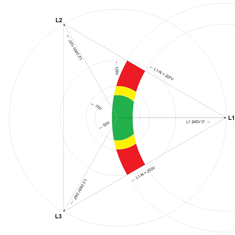
so the coloured regions are were the device thinks all is well - green where the N/PE voltage is actually ≤50V from true Earth, yellow between 50V and 70V (usually deemed acceptable for EV situations) and red where the device thinks all is well but the N/PE voltage is actually in excess of 70V from true Earth (anything up to 128V in this particular example). For the remaining unshaded areas of the triangle, the device will see L-N out of range and disconnect. Does that all make sense?

I've had to make an assumption about the actual line voltage present - since the N/PEN voltage is measured against that - I picked 240V as being typical for a UK installation, but of course it could vary considerably - which I suspect will mean that there could be an even wider range of PEN voltages that under particular circumstances the device would regard as being acceptable.

   - Andy.

  • Thank you to Andy for such a thoughtful posting.

    Of course, the question with any "voltage" is really the "potential difference", which begs the question, "between what and what?" I remain to be convinced by these open PEN devices. I shall stick with 3 phases 'cos at least you can compare the actual and theoretical values.

  • That is indeed a nice graphical way to show the blind spot or really I suppose the blind arc of the L-N test method. Any other voltage condition in the triangle would lead to automatic disconnection, and there is a lot more area there than in the arc.

    The question I suppose is how likely is an unlucky set of loads on the 3 phases that lands you into that blind zone, and is it likely that condition persists  long enough for someone to be hurt ?

    My mercifully  limited experience of lost neutrals, suggests that the other phases, especially the over-volted ones tend to load shed after a bit, so the phase balance is far from static, and as things switch on and off, the not really centre point voltage is pulled all over so a trip is likely shortly after the fault comes on if not immediately.

    Mike.

  • Does that all make sense?

    Yes

    I've had to make an assumption about the actual line voltage present

    This is quite tricky, as the supply voltage will vary - but if you think about it, the worst-case (largest red, or "non-correlation", area) is when the triangle is largest - i.e. when you have 400 V line-to-line.

    I have also sent you a PM.

  • I shall stick with 3 phases 'cos at least you can compare the actual and theoretical values.

    Until you have a prosumer's installation that generates on all phases when it switches to island mode (but remains connected to PME earthing arrangement) ...

    Of course, the question with any "voltage" is really the "potential difference", which begs the question, "between what and what?"

    Between Line and neutral at the charging point in the case of 722.411.4.1 (iv)

    Between PE and Earth at the charging point according to 722.411.4.1 (iii), although neutral to Earth would also achieve the same in a TN-C-S system.

  • Of course, the question with any "voltage" is really the "potential difference", which begs the question, "between what and what?"

    I my mind's eye the very centre of the triangle represents conventional 0V - i.e. the potential of the supply transformer's electrode and (providing there's no significant fault current flowing through the general mass of the earth) pretty much the assumed potential of the ground in general, including that of any car under charge (any local buried pipes connected to PME notwithstanding). So within a few assumptions the 50V, 70V and  128V circles represent what someone stood on the ground touching the car might be exposed to.

    the worst-case (largest red, or "non-correlation", area) is when the triangle is largest - i.e. when you have 400 V line-to-line.

    Or 440V? (corresponding to Uo=253V)

       - Andy.

  • So where are we in terms of a simple risk analysis, say using parameters like likelihood, severity, duration?

    Perhaps without any control measures at all the risk might be construed as low to begin with, depends I suppose on the weight one ascribes to the notion of severity. As GK has said before, measuring the voltage is better than doing nothing and certainly by adding a device to operate the contactor at around 18mA would seem to me to bring the risk level into the territory of tolerable.

  • So where are we in terms of a simple risk analysis, say using parameters like likelihood, severity, duration?

    Difficult. Statistical methods tend to make some assumtions or others - e.g. all starting conditions being equally likely - which may or may not be relaistic in practice.

    For instance, if we had a situation where L1 and L2 had similar loads on them and L3 was unloaded (perhaps not unreasonable if the break affected say a pair of semis) then the 400V between L1 and L2 would be shared roughly equally between the two sets of loads, so each seeing something near 200V. Being lower than normal L-N voltage there would perhaps be little chance of loads frying and so "automatically disconnecting" themseleves as it were, so the situation might persist for some time. On the diagram N would be about halfway along the straight-line between the L1 and L2 points - so could well fall into the red zone (depending on the exact figures involved).

    As Graham says, in practice things may well not be static though - even if nothing fries it's likely that some appliances will have change their consumtion from time to time - fridges will switch compressors off or on, thermostats on heaters will click. So things may swing into and out of the red areas. There's then the question of how the devices respond in that situation - do they latch off as soon as a voltage out-of-range event occurs or do they only remain switched off while the event persists and then re-close automatically when the voltage appears to be within range again? BS 7671 doesn't seem very specific on that point (it's not permitted to re-close while the voltage is still out-of-range, but doesn't specify whether than needs to be manual or can be automatic), and I can see arguments both ways - I can see a system that results in an entire neighbourhood finding their cars flat in a morning just because someone's vacuum clearer fused and the old BS 3036 fuse was a bit slow to clear the fault might not be entirely popular. C.p.c. current monitoring is certainly an extra safeguard, but not one that any standard currently insists on for these devices - so is that something we can rely on?

        - Andy.

  • Once all cars are electric, we're going to end up in a situation where one or two people a year die when touching their car after a PEN failure, while 2000 people a year die after they get in those cars and drive somewhere. We know which will make the headlines.

  • The IET states that an open pen detection device should only be used on a single phase installation, but many three phase car chargers are now not requiring an earth rod. I'm assuming they have a three-phase Pen fault device onboard. Is that right? has something changed that I'm unaware of?

  • but many three phase car chargers are now not requiring an earth rod.

    What type of 'three-phase car charger' are you talking about? Mode 3, Mode 4?

    I'm assuming they have a three-phase Pen fault device onboard. Is that right?

    Never assume. There are a number of issues at play here, and it might not be a simple answer to your question. In addition, if the charging equipment is manufactured for the global market, the manufacturer's installation advice may not be UK specific (and/or may not comply with BS 7671).

    In some Mode 4 charging points, the output may well be configured as an IT system, and the manufacturer may be recommending some form of means of earthing for the IT system. In some installations, it will be safer to connect this to the installation's means of earthing - in other circumstances, or where there is no open-PEN detection and there is a PME supply, a separated earthing system is necessary, but this should follow the same rules as separating TT where that is used.

    The requisite guidance on all of this is in the IET Code of Practice for Electric Vehicle Charging Equipment Installations, 4th Edition.