Following on from the recent discussion about the adequacy of open-PEN detection devices that disconnect when the L-N voltage goes outside of the 207-253V range and how, when the single phase installation is fed from a 3-phase supply system, some open-PEN situations might go unnoticed even though the PEN/PE voltage can be significantly higher than 70V from true Earth.
Can people check that I'm understanding this correctly please?
As I see it, once the PEN becomes disconnected, it's free to float from Earth and can therefore be dragged towards the various L1/L2/L3 voltages depending on any impedances left between the severed N and the line conductors (usually any connected loads).
So thinking about it in phasor diagram terms, you have the usual triangle formed by L1/L2/L3 and N can then be dragged to any position within that triangle.
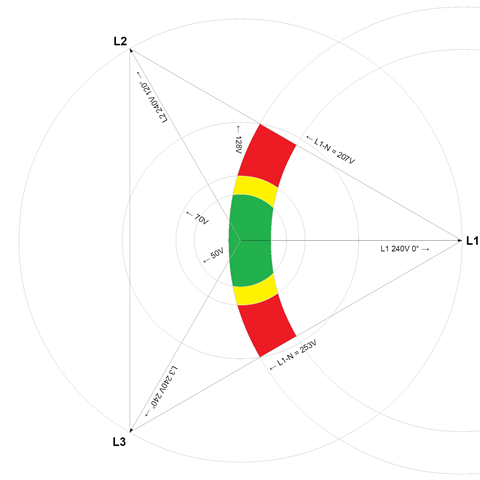
The detection device is looking at L-N voltages - or to put it another way, it's measuring the voltage on the N by using L as a reference. It's only seeing one phase, so can't work out anything about phase angles so it measures the magnitude of the voltage difference only - the phase angle of the measured L-N voltage could be anything. So I'm thinking that any given voltage different like that would show up on a phasor diagram as an arc (or circle) centred on the L position (L1 say) - the radius represent the magnitude of the voltage difference from L and the angle could be anything (within limits) - hence an arc rather than a single point.
So drawing arcs for the 207V and 253V from L, I get a region in between where the open-PEN device will think all is well.
So I've got this:

so the coloured regions are were the device thinks all is well - green where the N/PE voltage is actually ≤50V from true Earth, yellow between 50V and 70V (usually deemed acceptable for EV situations) and red where the device thinks all is well but the N/PE voltage is actually in excess of 70V from true Earth (anything up to 128V in this particular example). For the remaining unshaded areas of the triangle, the device will see L-N out of range and disconnect. Does that all make sense?
I've had to make an assumption about the actual line voltage present - since the N/PEN voltage is measured against that - I picked 240V as being typical for a UK installation, but of course it could vary considerably - which I suspect will mean that there could be an even wider range of PEN voltages that under particular circumstances the device would regard as being acceptable.
- Andy.