Dad my head hurts. Is this guy any good?
https://www.youtube.com/watch?v=eCqyvmRHBqw
Surely the R.C.B.O. would disconnect the supply within 20 to 30 mS with an earth fault, in reality Dad.
Z.
Dad my head hurts. Is this guy any good?
https://www.youtube.com/watch?v=eCqyvmRHBqw
Surely the R.C.B.O. would disconnect the supply within 20 to 30 mS with an earth fault, in reality Dad.
Z.

And? The problem here is that whilst everyone wants RCDs, they are not prepared to trust them! It seems to me that the RCD is being "perverted" to additional protection only, except in TT installations. Why is this, it is certainly not a requirement of BS7671?

The problem here is that whilst everyone wants RCDs, they are not prepared to trust them!
What is that based on?
RCDs can be used to provide the sole means of fault protection for ADS, at least since 17th Ed, BS 7671:2008. See Regulation 411.4.5
However, they cannot provide protection against overcurrent.
In terms of ensuring an RCCB isn't overstressed by earth fault currents, suitable overcurrent protection is required.
What are we looking at here? I have a 63 A RCCB. It is protected upstream by an overcurrent protective device, rated in accordance with the manufacturer's instructions, or a suitable device operating within the parameters of the largest device according to the manufacturer's rating.
So, for all earth faults up to 63 A, the RCCB can provide fault protection. For faults exceeding that, tbe RCCB is backed up by an overcurrent protective device which can protect the RCCB from harmful earth fault currents ... and also operates on Line-Line or Line-Neutral faults (as appropriate for the installation).
There is no quoted let-through energy for RCCB's, because they require a form of upstream overcurrent protection. To size conductors, you need to use the ratings of the overcurrent protective device.
So, you might ask, what about TT systems?
Well, if I were to ask a group of electricians how they measure the prospective earth fault current in a TT installation, they would say by taking an EFLI measurement to the earth electrode disconnected from the MET.
NOW, this is perfectly correct, for the worst-case conditions for ADS.
BUT it is NOT correct for the worst-case conditions in relation to protection against overcurrent (in this case, earth fault current).
Let me provide a simple example.
I have an earth electrode in a TT installation, RA = 80 Ω, and a combined supply loop impedance (supply earth electrode RB plus transformer plus line conductor) Z0 = 5 Ω. So, Ze = 85 Ω, and I think I have an Ief = 230/100 = 2.7 A. (And of course I use this value for ADS calculations, meaning I have to use RCDs for ADS).
However, I connect extraneous-conductive-parts, which could be extensive steelwork, possibly LPS, or extensive buried metallic pipework, with equivalent combined earth electrode resistance of 1 Ω.
Now, my equivalent Ze = 6 Ω, and I have a fault current at the origin of an Ief = 230/21 = 38 A, and in this case, we might be looking at instantaneous tripping of mcb or RCBO for faults on some 6 A circuits, perhaps even some 10 A circuits.
In some cases, however, we might be talking about substantial earth fault currents when extraneous-conductive-parts are connected. For example, large steel-framed multi-tennant building where the first tennant gets a PME supply and the rest TT ... when extraneous-conductive-parts shared with the PME installation are connected, Ief could actually be kA (the same as an L-N fault), simply because they have a path back to the supply neutral through the PME service MET.
Now, my fault current is

And?
Yes David, And?
That`s exactly what I was attempting to illustrate here.
Putting aside short circuit and overload.
We might use a fuse for earth fault protection with no quibbles.
We might ditto use a MCB which may even trip on one of two elements .
We seem to have no quarms about either strangely enough..
We tend to see RCDs in addition to either fuses or breakers as back up or supplementary protection yet we seem a little hesitant to consider RCDs as primary or sole protection for some reason.
So RCD or Fuse or Breaker as sole protection for earth fault - I wonder how they`d be placed in order of merit from say contributors of this (or any other) forum?
And Why?
And is this logical?
So RCD or Fuse or Breaker as sole protection for earth fault - I wonder how they`d be placed in order of merit from say contributors of this (or any other) forum?
Again ... just so it's clear ...
An RCD can be used - ON ITS OWN - to provide fault protection for ADS.
However, in reality, the RCD CANNOT be used on its own, because it is incapable of providing protection against overcurrent, and therefore to protect against overcurrent from the earth fault current, it must be accompanied by an overcurrent protective device.
This is VERY clear in Reg 411.4.5.
We never would use an R.C.D. on its own without overload protection, by a fuse or M.C.B. that is normal practice.
I was thinking though that the energy let-through of an earth fault is limited by an R.C.D. as it limits the time that the fault current can flow, thus limiting the "t" term in the adiabatic equation I squared t.
Of course in the video example above, by the lecturer, he used an R.C.B.O. which is better as in some cases the R.C.D. will trip off quickly at lowish earth fault currents, OR trip off quickly with large fault currents
411.4.5 line 4.
"Where an R.C.D. is used for fault protection the circuit shall also incorporate an overcurrent protective device in accordance with Chapter 43."
Z.
Graham, would be be happy if we thought of it in this way? an RCD on it`s own may be used for protection against earth faults.
However the RCD itself must be protected by a suitable overcurrent protective device.
Net result in actuallity , an RCD must be used in combination with an OPD
(an RCBO might be considered as one way of achieving this)
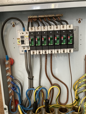
Not sure if you can make this out on this single phase installation. The Device is a 100A time delay 100mA RCD with a stated Im of 1000A. Upstream DNO 80A 1361 2B fuse.
Ipf is circa 2KA on both LtoN and LtoE.
My understanding of the IM value is that it relates to current in the live conductors and where a 100A RCD is used the upstream fuse should be one step down, in this case 80A.
There is no mention of the IdeltaM value on the device. Any thoughts?
We're about to take you to the IET registration website. Don't worry though, you'll be sent straight back to the community after completing the registration.
Continue to the IET registration site