This discussion is locked.
You cannot post a reply to this discussion. If you have a question start a new discussion

Smart relays on ring mains

Hi, 

I have installed plenty of these devices, as well as their dimmer range. 

https://shelly.cloud/products/shelly-1pm-smart-home-automation-relay/

What I am seeing however, is a number of people within online forums, installing these smart relays on ring mains. What they are doing is spurring from a ring, in 2.5mm and then switching this spur with the relay (without any form of fusing down, via means of an FCU). 

I do not believe this is compliant, for the following reason: 

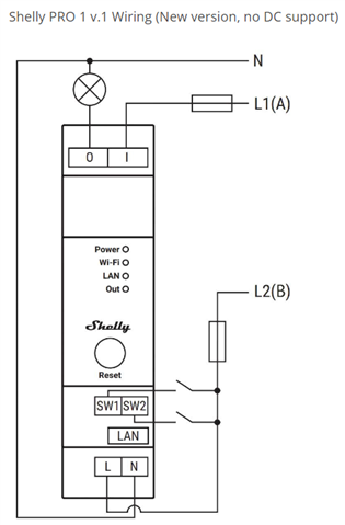
  • The relay is rated at 16A, and although it has overload protection, this is electronic and if the contact welds, the overload would not be broken by the relay itself.

If installed after a 13A fused connection unit, the device is not only protected by a 13A fuse (less than the contact rating) it is also then seen as some sort of appliance. 

Is there anything else to add to this? 

Would anyone here actually install these relays in-line with a ring main and if so, why/how does this comply with BS7671? 

A few people have stated that the likes of Click Smart have a similar setup in a double socket: 

https://click-smart.com/products/mode-smart-sockets

However these are covered by a product standard and not BS7671, so the application is very different. 

Thoughts? 

Parents
  • I recently ordered a Shelley Pro 1 https://shelly.cloud/knowledge-base/devices/shelly-pro-1/

    for a museum installation and to my dismay discovered that the primary power with this new version module was mains in only not 12V dc earlier version.  I understand from the vendor that this product has UL and FCC  AU/NZ CE approvals. However, I would seriously question the safety of a product that is din rail mounted with a gap of barely 2mm between the metal conductors between the screw terminals. I would leave an air gap of at least 5mm for L-N separation.

    Note that I have informed the vendor of my opinion and will definitely not use this module in our current project.

    Thoughts, please?


Reply
  • I recently ordered a Shelley Pro 1 https://shelly.cloud/knowledge-base/devices/shelly-pro-1/

    for a museum installation and to my dismay discovered that the primary power with this new version module was mains in only not 12V dc earlier version.  I understand from the vendor that this product has UL and FCC  AU/NZ CE approvals. However, I would seriously question the safety of a product that is din rail mounted with a gap of barely 2mm between the metal conductors between the screw terminals. I would leave an air gap of at least 5mm for L-N separation.

    Note that I have informed the vendor of my opinion and will definitely not use this module in our current project.

    Thoughts, please?


Children
  • can you post a pic of the offending terminals on the new model ? It is non too clear from the weblink, and the risks for clearance (a free air gap) and creepage (the distance electricity would have to flow along the  wiggles of a surface if it was say damp or contaminated) are quite fifferent and depend on the details of the design.

    Oddly when this thread was first opened I did contact the suppliers technical folk, who were kind enough to reply by email from Bulgaria, but the response was not exactly unequivocal and as feared they were indeed a bit shaky on UK wiring practice.
    Mike.

  • Hi, 

    I think there are many products on the market that have L&N side by side. Look at LED drivers for example.

    Can you elaborate more on your meaning? 

  •   So it's the terminals on the bottom of the device. 5mm

    pitch. The lower ones are obscured but on the same pitch as the higher level, screw terminal is shown. I've since returned the unit and have not taken any images other than a side profile, unfortunately.   Yes a company based in Sofia

  • The product compiles with required standards and carries a CE mark. I am also pretty sure Shelly use external labs for the certification of products as many of them are also UL listed for the states. 

    Where does this 5mm distance come from?

  • Yes, I understand they have approvals. So the terminals are on a 5mm pitch but the screws mean the gap between L and N is barely 2mm. These same terminals were used for a low dc voltage on an earlier model which I was comfortable with. 5mm min is my own rule of thumb when designing pcbs