This discussion is locked.
You cannot post a reply to this discussion. If you have a question start a new discussion

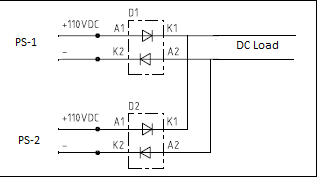
Diodes connected to 110VDC Positive & negative supply.... two 110vDC power supply's are connected in parallel.

Dear Team,

We have two power supply's 110VDC connected in parallel to each other. Power diodes are being used in both 110VDC power supply's. I can understand the use of diode in Positive supply, it can block the reverse current flow in other power source if one of Power supply voltage get drop or failed. But what is the sue of diode in negative supply of 110vdc. Pl refer the attached screen shot & share your valuable comments. 
Parents
  • I would take out the diodes in the negative line  I can't see they even have a reason to be there. My mate had 2 10 amp 13.5 volt psu both proper transformer supply's anyhow he used a diode in the positive line of each unit to stop backfeeding but solidly linked the negatives

  • I would take out the diodes in the negative line 

    Oooh - definitely not in mid-point earthed systems, and some other applications like DC charging batteries feeding inverters. If the -ve line is not "common" as Mike says, it's effectively another line conductor, with opposite polarity.

  • And as above in systems where the negative is common, and does not have series metering, or float, it makes perfect sense, so your mate is perfectly OK, in a 'negative earth' world where both supplies and the load are known. Not all systems are like that. If you make kit that may be used anywhere you have to assume it may not be.

    Mike

Reply
  • And as above in systems where the negative is common, and does not have series metering, or float, it makes perfect sense, so your mate is perfectly OK, in a 'negative earth' world where both supplies and the load are known. Not all systems are like that. If you make kit that may be used anywhere you have to assume it may not be.

    Mike

Children
No Data