This discussion is locked.
You cannot post a reply to this discussion. If you have a question start a new discussion

Diodes connected to 110VDC Positive & negative supply.... two 110vDC power supply's are connected in parallel.

Dear Team,

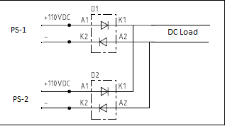
We have two power supply's 110VDC connected in parallel to each other. Power diodes are being used in both 110VDC power supply's. I can understand the use of diode in Positive supply, it can block the reverse current flow in other power source if one of Power supply voltage get drop or failed. But what is the sue of diode in negative supply of 110vdc. Pl refer the attached screen shot & share your valuable comments. 

  • You don't say much about the DC supplies PS-1 and PS-2 themselves.

    The diodes would definitely be required in some circumstances, e.g. mid-point earthed systems.

  • Hi, The 110VDC supply's are coming from two different Battery chargers. So here two different 110VDC supply connected in parallel to form the redundancy & further feeding to common DC load. 

  • How is the battery (or DC system) earthed? Positive, negative, mid-point, or unearthed?

    If the battery is mid-point earthed, then the diodes will be required as per a mid-point earthed source.

    It would be unusual for a secondary battery installation to be floating unless it's used with an inverter system? If it's used with an inverter system, then that is the reason for the diodes, as the DC system will "pivot" around supply neutral.

  • The idea that the two diodes in the positive lines prevent feedback from one supply to the other, works only when the negative rails are common, as which ever supply is more positive the diode to the other supply is reverse biased (indeed no current can flow either way through  an anti- series pair of diodes which is in effect what D1 and D2 are)

    But as Graham notes, there may be a very good reason NOT to have the negative rails in common, either to break an earth loop, or to avoid problems during a fault to ground from one line or the other or indeed from the middle of the battery pack. And as a catch-all for this another pair of anti-series diodes, from the lower halves of D1/D2 is a cheap and easy solution.

    It is also the sort of thing we do with electronics that takes shore power and vehicle battery power when we are not too sure what the vehicle is going to be and if there is an earth path or not. (along with protecting against a whole load of other things like over voltage and reverse polarity sudden shut off and a really nasty surge test.)
    Mike

  • I would take out the diodes in the negative line  I can't see they even have a reason to be there. My mate had 2 10 amp 13.5 volt psu both proper transformer supply's anyhow he used a diode in the positive line of each unit to stop backfeeding but solidly linked the negatives

  • I would take out the diodes in the negative line 

    Oooh - definitely not in mid-point earthed systems, and some other applications like DC charging batteries feeding inverters. If the -ve line is not "common" as Mike says, it's effectively another line conductor, with opposite polarity.

  • And as above in systems where the negative is common, and does not have series metering, or float, it makes perfect sense, so your mate is perfectly OK, in a 'negative earth' world where both supplies and the load are known. Not all systems are like that. If you make kit that may be used anywhere you have to assume it may not be.

    Mike

  • Even in "-ve earth" systems there might be a good reason for doubling up on the diodes - e.g. if you want the system to remain safe if one diode fails short-circuit. Of course you could just have two in series on the +ve line for the same effect, but one on each line may be simpler from a physical layout point of view.

       - Andy.