This discussion is locked.
You cannot post a reply to this discussion. If you have a question start a new discussion

How to twist wires together ... and how we used to do it.

Was browsing though YouTube when I saw (but don't advocate) this vid entitled 'Awesome Idea! How to twist electric wire together!': https://www.youtube.com/watch?v=qHoyF4yKhjU

Well, reminded me of how I was taught to solder joints on power cables, and also part of a book I have in my collection, entitled General Electrical Engineering edited by Philip Kemp MSc(Tech) MIEE AIMechE (which is undated, but I believe is from the late 1940s or early 1950s).

I hope I'm permitted to post the extract of the two pages I had in mind, as it's a very old publication:
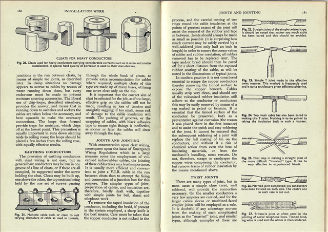
Certainly of interest, and shows there's a lot we used to know ... and how much depended on the skill of those who installed electrical equipment in days gone by.

Parents
  • How many of you were taught to use pliers to tighten the twist? I was taught not to because of the risk of damaging the strands.

  • That depends on the size of the conductors you are twisting ... and perhaps why ... e.g. if you don't make the joint tight enough before soldering, and solder flows between the strands, it's not a good joint.

  • I would use this type of joining... for a draw wire... 

    regards

  • Or even using an old cable to draw in a new one.

  • Hi Graham,

    if you ...solder flows between the strands, it's not a good joint
    I know you have said something similar in another thread, and I want to respectfully disgree, and to  point out that it is not seen as current best practice by the likes of IPC (*). - for strong joints and maximum current handling you do want the solder to wick between  strands and between the turns of one wire around another or around a solder terminal as fully as possible (actually they require at least  75% coverage on inspection as a pass). Further to ensure that the joint  meets or exceeds the current rating of the original wires, you need to have an overlap length of several cable diameters. What you do not want is inclusions (bubbles of air or flux or other 'foreign objects').

    However, where solder flow between wire strands and turns of wire can give rise to a problem is in terms of mechanical strength - there is a problem of fatigue fracture at the end of the stiff region. There can also be a problem with the solder creeping ands relaxing the joint pressure from un-sprung terminals - so choc bloc is a poor choice...

    Electrically the resistance of solder in a joint is similar to that of steel, being about 10 times that of pure copper and the cross sections of areas of contact need to allow for that.

    Mike

    (*) I am aware this is an electronics standards organization, and 3/4 of its texts relate to PCB design and terminating connectors inside equipment, but the physics really should be the same.

    From IPC J-STD-001E section 5,3

    "Tinning of Stranded Wire
    Portions of stranded wire that will be soldered shall be tinned prior to mounting when:

    a. Wires will be formed for attachment to solder terminals.
    b. Wires will be formed into splices (other than mesh) and optional when heat shrinkable solder devices are used.
    Solder wicking shall not extend to a portion of the wire which is required to remain flexible. The solder shall wet the tinned portion of the wire and should penetrate to the inner strands of the wire."

  • if you ...solder flows between the strands, it's not a good joint
    I know you have said something similar in another thread, and I want to respectfully disgree,

    So, it's an old 'rule of thumb' and as such 'more correct' in some cases than others.

    solder flow between wire strands and turns of wire can give rise to a problem is in terms of mechanical strength

    And that also depends on whether you are going to pot the connection or not, and the axial stress if it's suspended, or you don't have support immediately either side of the joint. Much less of a problem if you are going to pot it properly.

    Electrically the resistance of solder in a joint is similar to that of steel, being about 10 times that of pure copper and the cross sections of areas of contact need to allow for that.

    I guess that's an important thing, but of course there's a difference between current flow power cables for AC vs DC, and the type of joint would need to take that into account too.

    (*) I am aware this is an electronics standards organization, and 3/4 of its texts relate to PCB design and terminating connectors inside equipment, but the physics really should be the same.

    Definitely.

  • Haha, yes!

Reply Children
No Data