This discussion is locked.
You cannot post a reply to this discussion. If you have a question start a new discussion

How to measure common mode voltage and current?

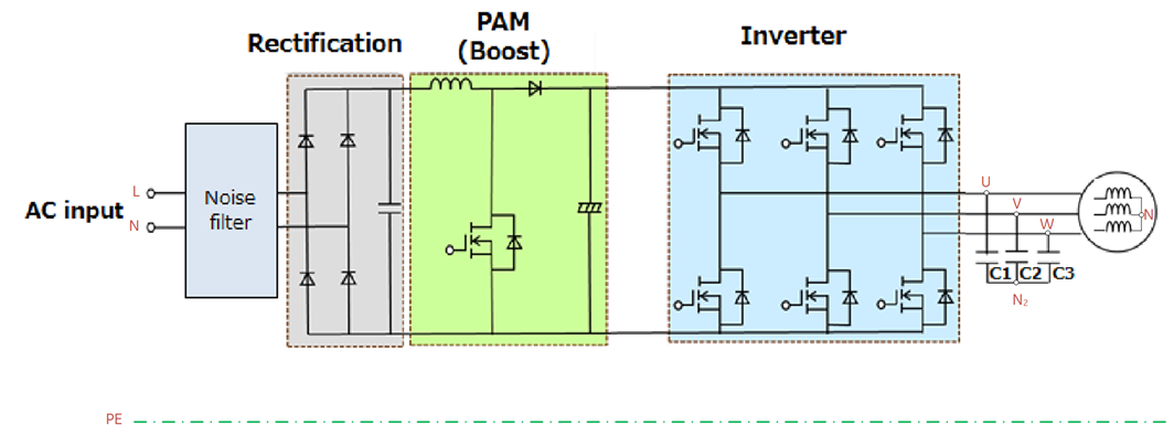
I have a system similar to this one. I have to measure common mode voltage and current to see how the inverter switching is affecting a common mode voltage and if I need to add common mode filter between the inverter and the motor.

For common mode voltage should I just put multimeter (ac settings) or differential probe between motor's neutral and PE? Would that be the same voltage as between N1 (filter capacitor's neutral) and PE?

How to measure common mode current? It that the same as leakage current? ... which shouldn't be higher than 0.5 mA or 3.5 mA.
Parents
  • Ah you have been handed the poison chalice of 'just measuring'.

    First, if you are looking to see if you need to be adding filtering, it will not be just mains frequencies you are interested in, so the normal meter on the AC setting will probably not do - a scope or even a measuring receiver or a spectrum analyser may be more use as the switching spikes will extend to some MHz spectrally speaking (due to microsecond risetimes.)
    Measuring common mode current for EMC purposes is commonly done with a clamp meter with a ferrite core and a dummy load and the instruments on the secondary. Measuring common mode voltages does require some thought as to 'relative to what exactly '  and in a professionally setting normally involves a LISN. (more info)

    The limits you will be looking at will not be expressed in volts and milliamps, but as power in  a given spectral bandwidth and this can be hard to deduce

    This sort of thing ( many thanks to Tim for putting his course notes on-line)

    Mike

Reply
  • Ah you have been handed the poison chalice of 'just measuring'.

    First, if you are looking to see if you need to be adding filtering, it will not be just mains frequencies you are interested in, so the normal meter on the AC setting will probably not do - a scope or even a measuring receiver or a spectrum analyser may be more use as the switching spikes will extend to some MHz spectrally speaking (due to microsecond risetimes.)
    Measuring common mode current for EMC purposes is commonly done with a clamp meter with a ferrite core and a dummy load and the instruments on the secondary. Measuring common mode voltages does require some thought as to 'relative to what exactly '  and in a professionally setting normally involves a LISN. (more info)

    The limits you will be looking at will not be expressed in volts and milliamps, but as power in  a given spectral bandwidth and this can be hard to deduce

    This sort of thing ( many thanks to Tim for putting his course notes on-line)

    Mike

Children
No Data