This discussion is locked.
You cannot post a reply to this discussion. If you have a question start a new discussion

How to measure common mode voltage and current?

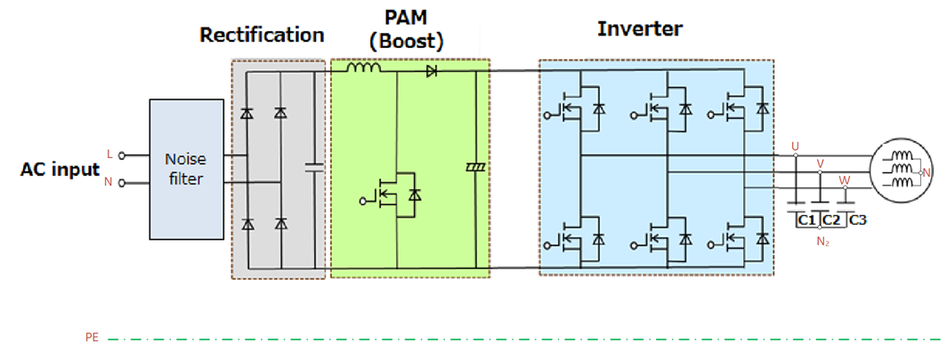
I have a system similar to this one. I have to measure common mode voltage and current to see how the inverter switching is affecting a common mode voltage and if I need to add common mode filter between the inverter and the motor.

For common mode voltage should I just put multimeter (ac settings) or differential probe between motor's neutral and PE? Would that be the same voltage as between N1 (filter capacitor's neutral) and PE?

How to measure common mode current? It that the same as leakage current? ... which shouldn't be higher than 0.5 mA or 3.5 mA.

Parents
  • Good answer Mike! I however have a question, "why do you want to do these measurements?". As Mike says they are difficult and will probably not give you any useful information. If you are hoping to get a rating for C1,2,3, or a current in N2, the answer is more easily calculated than measured. The EMC result from proper measurement with a measuring receiver is dependent on many things, particularly the type and length of the motor cable, its enclosure, perhaps conduit if long, and the effectiveness of the Earth path at higher frequencies than the switching frequency ( a few kHz). The 50Hz leakage will depend on the mains filter and general capacitance to Earth of everything. I would not expect to meet 3.5mA with a VFD of any significant size, and there is zero reason to worry about it as connection via an RCD would not be required, or if the system is TT the value could be set much more than 30ma. So why?

Reply
  • Good answer Mike! I however have a question, "why do you want to do these measurements?". As Mike says they are difficult and will probably not give you any useful information. If you are hoping to get a rating for C1,2,3, or a current in N2, the answer is more easily calculated than measured. The EMC result from proper measurement with a measuring receiver is dependent on many things, particularly the type and length of the motor cable, its enclosure, perhaps conduit if long, and the effectiveness of the Earth path at higher frequencies than the switching frequency ( a few kHz). The 50Hz leakage will depend on the mains filter and general capacitance to Earth of everything. I would not expect to meet 3.5mA with a VFD of any significant size, and there is zero reason to worry about it as connection via an RCD would not be required, or if the system is TT the value could be set much more than 30ma. So why?

Children
No Data