This discussion is locked.
You cannot post a reply to this discussion. If you have a question start a new discussion

What earthing arrangement is this and will RCDs operate

Hi, 

I found the below image on an IET forum. 
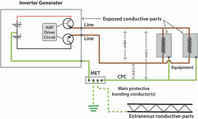
electrical.theiet.org/.../

The voltage potential between L&N (well, line and line) is 230V, with the voltage between each of these lines and the CPC sitting at 115V. 

The article states this is a TN-S earthing arrangement if a reference to earth is made using a rod, however I note there is no N-E relay/bond. 

Can anyone confirm this is correct and that this is indeed a TN-S earthing arrangement? 

Will RCDs connected to the output of the supply operate correctly, I presume so because current can flow between line(s) and CPC. 

Thanks. 

Parents
  • Any real one probably has a totem pole of 2 transistors per phase with some cunning 'flying deck' electronics to ensure the transistor turn on/off  voltages to follow the output voltage up and down without accidentally turning the transistors back on at the wrong moment.   Actually many small inverters single and 3 phase are a bit like a fully floating version of this where the batteries are replaced by a pair of smoothing capacitors charged by some supersonic screamer of an inverter. The clever ones even modulate the target output voltage  of the inverter to create an approximate  half sine profile at 100Hz , while the 3 phase ones instead go for a static DC bus value and pulse-width modulate the totem pole transistors to give a rectangular thing whose average if smoothed out over many cycles of the supersonic frequency provides the desired sine-like profile.
    mike.

Reply
  • Any real one probably has a totem pole of 2 transistors per phase with some cunning 'flying deck' electronics to ensure the transistor turn on/off  voltages to follow the output voltage up and down without accidentally turning the transistors back on at the wrong moment.   Actually many small inverters single and 3 phase are a bit like a fully floating version of this where the batteries are replaced by a pair of smoothing capacitors charged by some supersonic screamer of an inverter. The clever ones even modulate the target output voltage  of the inverter to create an approximate  half sine profile at 100Hz , while the 3 phase ones instead go for a static DC bus value and pulse-width modulate the totem pole transistors to give a rectangular thing whose average if smoothed out over many cycles of the supersonic frequency provides the desired sine-like profile.
    mike.

Children
No Data