This discussion is locked.
You cannot post a reply to this discussion. If you have a question start a new discussion

What earthing arrangement is this and will RCDs operate

Hi, 

I found the below image on an IET forum. 
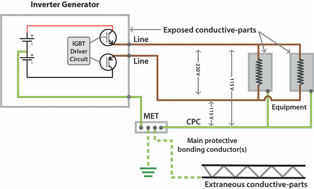
electrical.theiet.org/.../

The voltage potential between L&N (well, line and line) is 230V, with the voltage between each of these lines and the CPC sitting at 115V. 

The article states this is a TN-S earthing arrangement if a reference to earth is made using a rod, however I note there is no N-E relay/bond. 

Can anyone confirm this is correct and that this is indeed a TN-S earthing arrangement? 

Will RCDs connected to the output of the supply operate correctly, I presume so because current can flow between line(s) and CPC. 

Thanks. 

  • A version of centre tapped to earth, similar to 110 volt tool transformers.

    There two sets of circuits, the DC circuit from the batteries and the AC circuit, I will suggest that the “earth” connection is actually grounding the DC inverter supply from the batteries. 

  • Imagine this scenario.

    New build house with a combi-boiler that has wireless controls, the copper gas pipe does not have a Main Protective Bond because the supply is through a plastic pipe and the heating system has plastic pipework as well.

    The homeowner buys an inverter generator and then disconnects the boiler electric supply flex from the installation and fits a plug to the flex to supply it from the generator.

    The boiler will not run because the flame sensor completes its circuit through the body of the boiler and the earthing system.

    So the home owner fits a neutral/earth link inside the new boiler plug.

    Will the boiler run and if so why, conversely if not why; and will the boiler or generator be damaged doing so?

  • It would be a type of TN system. Whether RCDs would operate or not is one question (you'd need to know the source impedance to determine 100 %, but probably except in certain cases where the RCD has an FE connection) - however, whether the RCD test button will operate is a further question. Where the test button circuit uses outgoing line and incoming neutral, there should be no problem, but where FE is used for the RCD, possibly not.

    The article states this is a TN-S earthing arrangement if a reference to earth is made using a rod, however I note there is no N-E relay/bond. 

    Whilst this arrangement is used in certain situations, it is not suitable (at least as shown) for Prosumer's Electrical Installations for systems that are sometimes connected to the grid, and sometimes battery, as discussed in Chapter 82.

    The reason for this, is that, in connected mode there will be an effective "fault" between Line or Neutral (swapping 100 times per second), and this will operate RCDs. It is also contrary to the general requirements of BS 7671 and also, effectively, ESQCR.

    To make this work in a Prosumer's Electrical Installation, the N-E bond relay would be required between MET and the battery mid-point. BUT opening the battery mid-point in connected mode means the battery floats - meaning the DC side would need to be double or reinforced insulation or equivalent, rather than "TN-S DC".

    And it is that reason why the IET CoP for Electrical Energy Storage Systems shows the N-E bond being made to the AC Neutral.


    There are, perhaps, ways of making a TN-S DC battery work, but it would require isolation in the inverter (and still an N-E bond to AC Neutral), or an arrangement where the battery inverter is only used when the grid fails - although the latter is really a type of UPS that has a "break before make" transfer and therefore not really ideal for either UPS or for energy storage in a prosumer's electrical installation.

  • I presume that the IGBT arrangement is merely "symbolic" - the way it's draw it would seem only to be able to switch d.c. rather than produce a.c....

       - Andy.

  • Thanks for your input 

  • Thanks for your input 

  • Thanks for your input 

  • I presume that the IGBT arrangement is merely "symbolic" - the way it's draw it would seem only to be able to switch d.c. rather than produce a.c....

    Strictly, yes, half-bridge inverters exist, although free-wheeling diodes would be required across each transistor, and the load Neutral would return to the mid-point of the battery.

  • Any real one probably has a totem pole of 2 transistors per phase with some cunning 'flying deck' electronics to ensure the transistor turn on/off  voltages to follow the output voltage up and down without accidentally turning the transistors back on at the wrong moment.   Actually many small inverters single and 3 phase are a bit like a fully floating version of this where the batteries are replaced by a pair of smoothing capacitors charged by some supersonic screamer of an inverter. The clever ones even modulate the target output voltage  of the inverter to create an approximate  half sine profile at 100Hz , while the 3 phase ones instead go for a static DC bus value and pulse-width modulate the totem pole transistors to give a rectangular thing whose average if smoothed out over many cycles of the supersonic frequency provides the desired sine-like profile.
    mike.

  • Figure 4 ‘Floating’ generator configuration