This discussion is locked.
You cannot post a reply to this discussion. If you have a question start a new discussion

What earthing arrangement is this and will RCDs operate

Hi, 

I found the below image on an IET forum. 
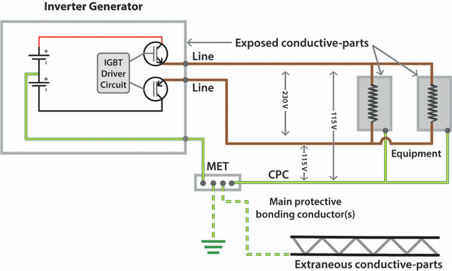
electrical.theiet.org/.../

The voltage potential between L&N (well, line and line) is 230V, with the voltage between each of these lines and the CPC sitting at 115V. 

The article states this is a TN-S earthing arrangement if a reference to earth is made using a rod, however I note there is no N-E relay/bond. 

Can anyone confirm this is correct and that this is indeed a TN-S earthing arrangement? 

Will RCDs connected to the output of the supply operate correctly, I presume so because current can flow between line(s) and CPC. 

Thanks. 

Parents
  • the AC earth connection would be at +12 vDC to the chassis

    I'd hope that no-one would arrange it like that as any connection between an (a.c.) exposed-conductive-part and the chassis (quite likely for a fridge) would short out one of the batteries. Normally the chassis would be the common 0V reference for all systems.

    The boiler will not run because the flame sensor completes its circuit through the body of the boiler

    Does it rely on the c.p.c and N-PE link though? When that bit failed on my main 24 and I cut apart the epoxy encapsulated unit (just to see if I could see what had gone phut and if I really needed to pay several tens of pounds for a new one next time) as well as a few electronic components, there seemed to be a small transformer - which I presumed generated HV between the electrode with the chassis - so the loop seemed to be contained within the appliance. other makes/models could be quite different of course. Relying on an external N-PE link - feels a bit dodgy to me - how would it work in those parts of the world where the supply may be 220V between two lines?

    but there could be 120 volts on the earthed metalwork of the boiler.

    Depends what you're measuring against. If you earth one pole from the generator then that's normally deemed to be 0V - what used to be the centre point would now be at 120V and the other line at 240V. Of course you wouldn't choose to do that if the centre point of the 'battery' side was also earthed and you didn't have separation between the d.c. and a.c. sides, as, again, you'd end up with a short.

            - Andy.

Reply
  • the AC earth connection would be at +12 vDC to the chassis

    I'd hope that no-one would arrange it like that as any connection between an (a.c.) exposed-conductive-part and the chassis (quite likely for a fridge) would short out one of the batteries. Normally the chassis would be the common 0V reference for all systems.

    The boiler will not run because the flame sensor completes its circuit through the body of the boiler

    Does it rely on the c.p.c and N-PE link though? When that bit failed on my main 24 and I cut apart the epoxy encapsulated unit (just to see if I could see what had gone phut and if I really needed to pay several tens of pounds for a new one next time) as well as a few electronic components, there seemed to be a small transformer - which I presumed generated HV between the electrode with the chassis - so the loop seemed to be contained within the appliance. other makes/models could be quite different of course. Relying on an external N-PE link - feels a bit dodgy to me - how would it work in those parts of the world where the supply may be 220V between two lines?

    but there could be 120 volts on the earthed metalwork of the boiler.

    Depends what you're measuring against. If you earth one pole from the generator then that's normally deemed to be 0V - what used to be the centre point would now be at 120V and the other line at 240V. Of course you wouldn't choose to do that if the centre point of the 'battery' side was also earthed and you didn't have separation between the d.c. and a.c. sides, as, again, you'd end up with a short.

            - Andy.

Children
No Data