This discussion is locked.
You cannot post a reply to this discussion. If you have a question start a new discussion

What earthing arrangement is this and will RCDs operate

Hi, 

I found the below image on an IET forum. 
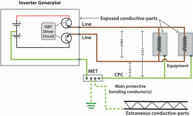
electrical.theiet.org/.../

The voltage potential between L&N (well, line and line) is 230V, with the voltage between each of these lines and the CPC sitting at 115V. 

The article states this is a TN-S earthing arrangement if a reference to earth is made using a rod, however I note there is no N-E relay/bond. 

Can anyone confirm this is correct and that this is indeed a TN-S earthing arrangement? 

Will RCDs connected to the output of the supply operate correctly, I presume so because current can flow between line(s) and CPC. 

Thanks. 

Parents
  • but vehicles can be positive earthed and with a First Fault on some wiring systems the vehicle body and chassis could be at a higher voltage without any one getting a shock.

    Ah yes - +ve earth systems can be fun - my parents had a Morris Traveller at one time, and the local garage couldn't figure out why the battery kept going flat - until someone noticed they'd put the battery back in a "conventional" manner - it mostly worked OK, until the battery started to run down and the regulator switched the dynamo in ... which then actively discharged the battery!

    First faults on +ve earth systems should disconnect in just the same was as -ve earth though (creates a short and blows the fuse). Chassis wise both systems are at (conventional) 0V - it's the insulated wiring system that then differs - either +12V or -12V.  In normal circumstances you can touch bumpers without drama. It's the jump leads completing the circuit by connecting -12V to +12V or -12V to 0V or +12V to 0V that causes the issue.

       - Andy.

Reply
  • but vehicles can be positive earthed and with a First Fault on some wiring systems the vehicle body and chassis could be at a higher voltage without any one getting a shock.

    Ah yes - +ve earth systems can be fun - my parents had a Morris Traveller at one time, and the local garage couldn't figure out why the battery kept going flat - until someone noticed they'd put the battery back in a "conventional" manner - it mostly worked OK, until the battery started to run down and the regulator switched the dynamo in ... which then actively discharged the battery!

    First faults on +ve earth systems should disconnect in just the same was as -ve earth though (creates a short and blows the fuse). Chassis wise both systems are at (conventional) 0V - it's the insulated wiring system that then differs - either +12V or -12V.  In normal circumstances you can touch bumpers without drama. It's the jump leads completing the circuit by connecting -12V to +12V or -12V to 0V or +12V to 0V that causes the issue.

       - Andy.

Children
No Data