I am looking at a project in a fairly large residential property and trying to avoid a collection of small consumer units near the supply head.
Supply is TNCS, no measurements at this stage
The supply head is in an external meter box, I will be putting an additional box of some sort next to it.
Based on a rough initial plan, from the meter head there will be the following connections
60A sub main on 16mm SWA to main house DB
60A sub main on 16mm SWA to garage, feeding two EV chargers with load management on main feed and garage submain.
Assuming 16A connection on 10mm cable to solar panels in field 30 to 50m away
Assuming 16A connection to battery inverter 5m away
House is on fused connection taken from henley blocks in main meter box, plan to leave this as it is and then run tails from henley blocks to second meter box.
Question is what do I do there to support the 3 connections
Initial thought has been an IP65 enclosure with 3 MCB's, but then I have some concerns
- I don't think I can get an IP65 enclosure with a busbar capable of supporting 16mm cable for the load and MCB's for each of the circuits, with spare slots for future expansion
- Cables will be armoured clipped direct or underground in ducting
- Beginning to think a fused switch might be better for the garage to provide better selectivity, downside is that I will end up with an enclosure for each submain?
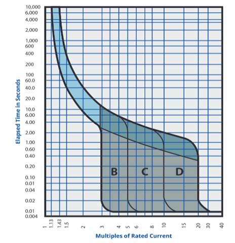
VD on garage submain 1.36% and for a 63A fuse with 5 second disconnect time max earth fault loop impedance is achievable at 1.07 ohms. DB in garage will be all RCBO. Garage will be a TT island
Solar and battery system not my responsibility but trying to take a holistic view on design of distribution at the supply head
Are there better ways to do this, enclosures that support cartridge fuses and circuit breakers, just go with metal CU in IP65 enclosure.
Given that the meter head is actually in an open log store next to the house I am swaying towards everything going inside a metal IP65 enclosure
Welcome your thoughts
