This discussion has been locked.
You can no longer post new replies to this discussion. If you have a question you can start a new discussion

Best solution for primary distribution in residential property

I am looking at a project in a fairly large residential property and trying to avoid a collection of small consumer units near the supply head.

Supply is TNCS, no measurements at this stage

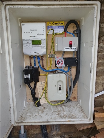
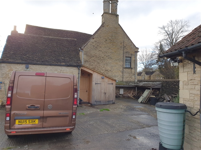
The supply head is in an external meter box, I will be putting an additional box of some sort next to it.

Based on a rough initial plan, from the meter head there will be the following connections

60A sub main on 16mm SWA to main house DB

60A sub main on 16mm SWA to garage, feeding two EV chargers with load management on main feed and garage submain.

Assuming 16A connection on 10mm cable to solar panels in field 30 to 50m away

Assuming 16A connection to battery inverter 5m away

House is on fused connection taken from henley blocks in main meter box, plan to leave this as it is and then run tails from henley blocks to second meter box.

Question is what do I do there to support the 3 connections

Initial thought has been an IP65 enclosure with 3 MCB's, but then I have some concerns

  • I don't think I can get an IP65 enclosure with a busbar capable of supporting 16mm cable for the load and MCB's for each of the circuits, with spare slots for future expansion
  • Cables will be armoured clipped direct or underground in ducting
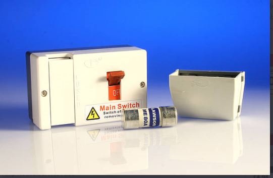
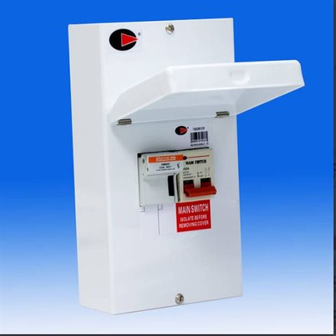
  • Beginning to think a fused switch  might be better for the garage to provide better selectivity, downside is that I will end up with an enclosure for each submain?

VD on garage submain 1.36% and for a 63A fuse with 5 second disconnect time max earth fault loop impedance is achievable at 1.07 ohms. DB in garage will be all RCBO. Garage will be a TT island

Solar and battery system not my responsibility but trying to take a holistic view on design of distribution at the supply head

Are there better ways to do this, enclosures that support cartridge fuses and circuit breakers, just go with metal CU in IP65 enclosure.

Given that the meter head is actually in an open log store next to the house I am swaying towards everything going inside a metal IP65 enclosure

Welcome your thoughts

  • I cannot see it of course, but another thought may be, depending how much space there is, and how damp it may get, would a second meter box next to the first one look too silly? Once inside that you can be a bit more relaxed about the weather ;-)  Steel and outdoors are not always the best of buddies, and if the floor is earth then maybe you do not want a big chunk of TNCs earth exposed ?

    Mike.

  • I

    Some pictures above, you can see the meter cabinet under the log store roof. It's a balance between shock risk and fire risk. 

    Also thinking things through I may leave the solar/ battery guys to install an extra meter box etc as the customer wants the battery to work in island mode and they are going to have to figure out how to disconnect the garage loads when in island mode. 

  • Solar and battery system not my responsibility but trying to take a holistic view on design of distribution at the supply head

    Inverters may need a second CU, that CU supplied by a fuse (rather than off henley blocks direct), due to a change in Regulation 551.7.2 in Amendment 2 (for consumer unit rating).

    The island mode "load shedding" is usually best achieved by the positioning of Island Mode Isolator, noting there's only limited power available in island mode (inverter output current).

    Where will the earth electrode for island mode be connected?

  • It's awfully crowded in there!

    I think that a second meter box is an excellent idea. Instead of multiple switch fuses (which would have the advantage of being able to isolate each distribution circuit independently) how about a 3-phase switch fuse?

  • Thanks so far for the comments.

    I am going to let the solar guys figure out the island mode switching. Given the way the installation is configured and locations of various sub boards they are going to have fun getting a sensible split. I don't think the customer or they have really considered how they are going to do things.

    Presumably the regs require the system design to prevent overload of the generation system in island mode rather than relying on the end user to moderate their usage. In which case the connection point is going to have to be somewhere in the house with suitable reconfiguration of consumer units.

    At this point I am going to leave the challenges to them and just ask them to leave me a connection point and space for a fused switch to feed the garage.

  • I am going to let the solar guys figure out the island mode switching.

    I'm not quite getting that.

    A coordinated design is required  (see also Chapter 82)... but perhaps more importantly CDM Regulations 2015 apply?

  • I am not saying I won't participate in the design process. But I feel that the solar/battery install will be making the biggest change and will be the most complex, also presumably the team doing this work will have the relevant knowledge and qualifications, I have no formal MCS training or qualifications.

    Therefore it's more appropriate for me to feed my requirements in to them and they take ownership of the overall design and the majority of the installation at the supply head. They can either install first or provide me with guidance on how to design my installation to make their job as easy as possible.

  • Therefore it's more appropriate for me to feed my requirements in to them and they take ownership of the overall design and the majority of the installation at the supply head. They can either install first or provide me with guidance on how to design my installation to make their job as easy as possible.

    No problem with that, and yes it makes a lot of sense.

    Just advising, though, that from a legal stand-point, even if the project is not notifiable, CDM Regulations requires all Contractors to know who's doing what before work starts.

    Who is the Principal Contractor (if there is more than one, there must be one)? If the Client is a domestic Client, the Principal Contractor also undertakes the Client's duties (which includes a responsibility to see the coordination of all this kind of stuff is done).

  • Initial thought has been an IP65 enclosure with 3 MCB's, but then I have some concerns

    I had a similar problem at home and ended up putting 3off 58x22 DIN rail fuse carriers in a sturdy DIN rail box together with a switch disconnector, a bus-bar and a few DIN rail terminal blocks. It does have the disadvantage of not being able to show on paper that it conforms with the various assembly standards. The only 'proper' approach I can think of of supplying several submains from HBC fuses without spending silly money is a few separate switchfuses and henley blocks (perhaps with a bit of trunking for the tails to make it looks a bit less like a dog's dinner) . That was one of the issues that the fictional "Concept" CU range was meant to address.

       - Andy.

  • I have just looked at a few fuse holders. Interesting to note that Eaton at least recommend only connecting high temperature wire, which when I think about it makes sense. Probably also means that plastic cases may be a bad idea. I still don't think there are any plastic IP65 enclosures on the market that include busbars capable of taking 16mm cable.

    From what I can see the smaller plastic switch fuses like the one below don't really work for terminating round xlpe cables and certainly not armoured cables. I also wonder how they would handle sitting at full load for 12 plus hours with a couple of cars charging.

    Which would force larger enclosures such as 

    At which point it's probably better to put multiple fuses in a larger frame. 3 phase units have quite a bit of space inside, presumably to deal with heat issues and I have seen that eaton suggest using high temperature wires for connections.

    In some ways using mcb's has it's appeal because presumably they won't generate as much heat when running close to limits. If a C curve was used what's the chance of nuisance tripping.