This discussion is locked.
You cannot post a reply to this discussion. If you have a question start a new discussion

Reduction of cross-sectional area between main isolator and auxiliary breaker

Hello,

I have a question regarding a specific topic.

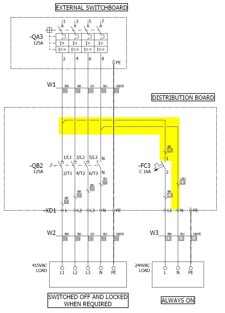
I need to create an isolation box with 2 specific goals:

1 - To ensure a specific load is off and locked

2 - To have a secondary supply for a secondary load ensuring it is always on

With that in mind, I have considered the solution as per example attached.

My question is related to the connection between the main isolator of the Distribution Board (-QB2) and the Auxiliary breaker (-FC3).

The protection to the Distribution Board is ensured by the breaker upstream at the External Switchboard (-QA3) which ensures both cables W1, W2 and the 3 phase load are protected.

The connections to the smaller breaker have a much reduced CSA than the main supply cable W1 (2,5 vs 50 mm2).

The breaker upstream will not protect the smaller CSA cable but that is the case on many situations when busbars are not used. The auxiliary breaker (-FC3) will protect the downstream cable W3 and the load because the rating is suitable from that point downwards. But not upstream this breaker. You can say it is unprotected.

I think this is still allowed in BS7671 on a specific article 434.2 Position of devices for protection against fault current (434.2.1) where some conditions need to be met including a limitation of length.

That is my question.

Am I interpreting this correctly?

The 3 phase load is a standard load not covered under the article 433.3.3.

Any feedback will be much appreciated.

Thank you

Kind regards

Parents
  • I suspect you might struggle to give 2.5mm² proper fault protection from a 125A OPD. The withstand for 2.5mm² is typically around S²k² - 2.5² x 115² = a little over 80,000A²s whereas a 125A BS 88 fuse has an energy let-through of somewhere between 100,000 and 200,000 A²s according to some manufacturers.  Other manufacturers may differ of course. I don't have any figures for MCCBs to hand, but it's not unusual for a circuit breaker to have a greater energy let-through than fuses when fault currents are high.

    So 434.2.1 may well be your way forward.

    On the other hand even a modest increase in c.s.a - say from 2.5mm² to 4mm² or 6mm² might well allow you to provide fault protection directly - all depending on the actual numbers of course.

       - Andy.

  • The 80 k j/ohms for 2.5mm is not the copper melting, it is the plastic being warmed so that when cooled it is then embrittled, and might crack if flexed. That sort of cable damage is not ideal of course, but not perhaps the sheets of flame and ejection of molten metal that some might be expecting. For that you need the Onderdonk formulae or something more accurate.
    Mike

Reply
  • The 80 k j/ohms for 2.5mm is not the copper melting, it is the plastic being warmed so that when cooled it is then embrittled, and might crack if flexed. That sort of cable damage is not ideal of course, but not perhaps the sheets of flame and ejection of molten metal that some might be expecting. For that you need the Onderdonk formulae or something more accurate.
    Mike

Children
No Data