
Ambient temperature of 38C, cable 70C, what is Ca?
If I do it Lyles way
10mm @ 90C 4 x 0.85 x 40.42 x 36 = 4.9 V drop
10mm @ 70C 3.8 x 0.85 x 40.42 x 36 = 4.7 V drop
10mm OK
I went for the easier![]()
As it's below 16mm and the reactive element can be ignored.
My Ib is 28000/1.732/400 plus pf 6.06A giving 46.46A
But went for a more conservative temp correction 4B1 0.91 (40C rather than the lesser 35C @ 0.96)
Either way it suggests a 10mm cable for It.
for a 10mm @ 90C thermosetting cable (4E4B-4) = 4 mV/A/m with 36m and 46.48A is 6.69V drop
for a 10mm @ 70C thermoplastic cable (4D4B-4) = 3.8 mV/A/m with 36m and 46.48A is 6.39 V drop
So a16mm is required for below 6 Volts dropped. (and keep the losses down)
![]()
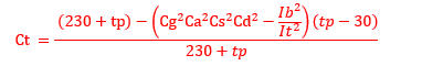
Jon, this is the general formula for voltage drop in BS7671. It applies to cables over 16mm2 where the reactance is tabulated. Candidates on the 2396 are expected to be able to manipulate it appropriately without access to programmes. For cables up to 16mm2 just drop out the + bit at the end.
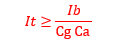
The Ct value is a correction for temperature and has an advantage where a cable is carrying much less than its design current. It is derived from;
In the Irish Regs, we do not have tables for voltage drop. We have to work out voltage drop from the resistivity of the conductor at operating temperature, knowledge of the load power factor and reactance of the cable. Generally, reactance can be assumed to be 0.08mohms per metre. If you look at say Table 4D4B you will see that 0.08 is approximately half the values given for single phase reactance in column 3 and if you multiply 0.08 by root 3 its not far away from the reactance values in column 4 for 3-phase.
There is no correction factor for cable temperature available as above but I guess it could be applied with justification.
The way set out in IS10101 2020 (Regs in Ireland) for copper is then;
(0.0225 * length/csa * cos theta + 0.00008 * length * sin theta) * Ib
The outcome is then multiplied by 2 for single-phase or by root 3 for 3-phase.
Which ever method you use, you will find that the minimum CSA for voltage drop for the question I posted allows 10mm2. to be used. The question did ask for the minimum value so whilst a basic calculation might indicate 16mm2 or 25mm2, which might pay for itself in the long run in terms of heat loss, the candidate would not get the full marks for that section.
For ccc, assuming overload in starter;
I have Ib at 47.6, Cg at 0.88 (subject to MapJ's point about 30% holes) and Ca at 0.96 which allows 10mm2.
By the way, you can only elect to go for Ib as the numerator where grouped cables are not subject to simultaneous overload if it is the greater of the two options given in equations 3 and 4 in 5.1.2 of appendix 4. It can be used in our case if the protective device is to provide fault protection only.
Interesting approach.
Why not put the pf in the volt drop calc.
Doesn't the cables being thermosetting or thermoplastic make a difference in there performance?
I don't have a cable calc software package, I wonder what Amtech would come up with?
One can make allowance in the volt drop calculation for load power factor to permit the use of 10mm2
mv|A|m (max) = 6*10³/47.6*0.85*36* = 4.12
Reference to Table 4D4B column 4 indicates that mv|A|m value of 10mm² is 3.4mv so 10mm² can be used to satisfy the 6v specification.
(Table 4D4B is used rather than 4E2B as the cable is not being run at 90C, however, applying the load power factor to the voltage drop calculation would still permit the use of 10mm2 if the candidate was referring to the latter table.)
Actual voltage drop = 3.4*0.85*47.6*36/1000 = 4.95v.
Actual voltage drop = 4*0.85*47.6*36/1000 = 5.8v using Table 4E2B.
Likewise 10mm2 can be used to satisfy current carrying capacity PROVIDING one selects an appropriate value of Ca (which was the crux of my original question).
Totally agree that there will be ambiguity.
The Chief Examiner constantly alludes to the need for candidates to set out their assumptions "at this level".
ah yes, the vd limit gets you, it cannot be 6mm, and maybe can't be 10mm either depending how hot it runs. sorry for missing that.
I do not like the form of words
" touching one other similar circuit which has a conductor operating temperature of 70°C"
to me that does not say a cable whose insulation can stand 70c, but rather this is the temp that the copper in that cable is already - i.e. it is fully loaded and cannot be grouped if it has 70c rated insulation or maybe it is square of 40/60ths of fully loaded if its insulation is good for 90 but the copper is at 70.
It is not clear, and it could legitimately be understood in more than one way.
Like my comment about the holes in some designs of tray, and if not enough then degrading from E to C, I am deliberately looking for trouble - I think I know what the examiners expect, but then they should be more careful with their questions.
Mike
Existing cable or not. I read it as the conductor temp of the adjacent cable is 70C meaning the cable was a 70C not a 90C type. The circuit is said to be similar design so assume a below 6 Vd max so I'd expect the cable not to be running anywhere near 70C.
Just another red herring.
Deliberately contentious. 
My workings slightly different but similar result.
40.42A per phase pf=0.85 (no mention of efficiency)
46.48A per phase In = 50A
Cg = 4C1-3 (0.88) Method 4A2-31 E or F
Ca = 4B1 (0.96)
It = 46.48 (Ib) x Cg x Ca = 54.91
5.1.2 For groups allow Ib instead of In, where simultaneous overload is unlikely.
Vd for 10mm swa 4 x36x46.48/1000 = 6.69V
Vd for 16mm swa 2.5x36x46.48/1000 = 4.18V
So 16mm wins the Volt drop requirement.
I could of course be completely wrong!
he hee
well, this will fail the CandG but maybe an OK method in real life.
KVA = KW/PF = 28/.85 = 33kVA
each phase 1/3as 3 phases so 11KVA/phase
Each phase 11000/230= 47,7 A at nominal load
call it 50A per line
Motor Overloads set to 50, backed by fuses a lot higher, or it wont survive switch on. If adjacent circuit is already running at 70C then no heating of any kind at all from this one is permitted as it will overheat the existing cable so do not risk it, cut the cable ties or undo the cleats and refit, with it moved it over a bit so not touching. Try and get at least one cable dia of gap for thermal independence.
Are you able to terminate this cable in a way you can run it to 90C? if not then that is a red herring, use figures for 70C max
38C derater from graph 0,9 so that 50A becomes 55A - you need a cable that would be OK on a tray carrying 55A at 30C
Now look very hard at the holes in the tray - more than 30% holes, cols E or F. less than 30% holes - and that is actually most univolt/CEF/TLC type stuff, then really it should be column C.
so depending on that result 6mm or 10mm swa ;-) I'd go for at least 10mm anyway, and get 1.6-1.9milliohms per core per metre, so at 36m and 50 A a bout 3,5 volts drop per core, and more like 5-6V off the 400V phase to phase voltage.
16mm would be a choice if grouping cannot be mitigated.
Deliberately Contentiously, Mike.
We're about to take you to the IET registration website. Don't worry though, you'll be sent straight back to the community after completing the registration.
Continue to the IET registration site
