Extending supply from one CU to the next with internal connectors

Just been browsing parts and seen these

https://mastertrade.co.uk/fusebox-it1002u-100a-2p-connector.html

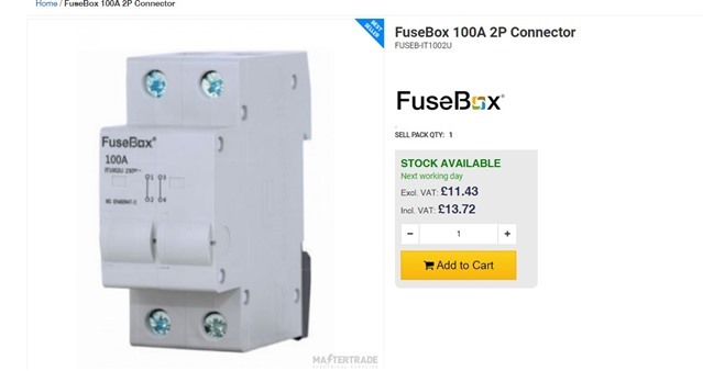
Wondering if in some cases they are a more elegant way of effectively splitting the supply to two consumer units.

Run supply into first unit and then use one of these to connect to the second unit. Struggling to get my head around how I would connect inside the consumer unit and maintain a supply capable of carrying ideally 100 amps.

Presumably the bus bar is ok if the connector is next to the incoming device, second board would use another one of these instead of a switch.

Then presumably use a short internal neutral cable from hager or similar from the neutral bar.

Wondering why I haven't seen others doing something like this. I am mainly looking at EV installs.

I assume these are aimed at when CU's are stacked and enabling effectively internal interconnection, where as for me I would probably have the boards next to each other, maybe with a gap. 

  • I have not used these, but  have seen a similar product by WAGO that takes cable that is sized more or less like  'meter tail' out of one DIN box into another. You may or may not retain the incoming switch in the second box. Not seen it in done a UK consumer unit, yet.
    ~Though it seems Ideal for those unfused submains that some folk seem to manage by tapping in at the main switch..

    Mike

  • Would make a lot more sense if they employed DP (L+N) bus bars.In a conventional setup it could only go on the far end of the bus-bar from the main switch and as you have have an additional tail to the N bar - which probably isn't idea. It could go next to the main switch and then use short tails for both L & N to supply the terminal block from the load side of the main switch (if the main switch terminals were capable of taking those in addition to the outgoing busbar) or even a short section or DP bus-bar (I've occasionally used DP forked bus-bar which sits under the terminal screw heads, leaving the cage clamp terminals free for extra conductors, but that only works with some styles of terminals).

    But yes, ideal for replacing the "main" switch on the 2nd unit to keep identifying the installation's main switch obvious.

       - Andy.

  • Thinking about it the one I saw was set up as  3 gangs, and on a 3 phase board, that made sense - one per phase, and neutral taken from a suitably large bolt somewhere else.
    In a single phase board, a single gang one replacing one MCB with a solid link would make more sense.  Do they make a single gang model ?
    Mike

  • The manufacturer's website (https://fusebox.co.uk) does not make it clear, but it could be used in a double row CU, preferably in series, not parallel. ;-)

  • Wylex do this single module, which I think, based on the images, is used in their duplex boards  Wylex NHSPDC

  • Couldn't find the product on that site Chris, although well done for finding it, searching for fusebox comes up with allsorts. So haven't seen the data sheet for it.

    I am also struggling to see how this works, apart from as a replacement to a main switch in the second CU.

    Used as a splitter in the first CU, the diagram on the front suggests that the bottom terminals use two prongs of the live busbar, which makes sense since the MCB prongs are usually thinner than the main switch prongs. But they aren't joined within the device (makes sense if used instead of main switch in second CU, L&N separate) so if only one terminal at the top is used for 100A at the second CU, it is fed from one smaller prong on the busbar! It would make sense if both top terminals were used and the cables spliced to go to the second CU, but what would the point be in that?

    Unless fusebox busbar prongs are all the same width each capable of carrying 100A.

  • I am not really liking this idea, it depends on too many assumptions about current handling of the (small) busbars in CUs. Why don't you like Henly blocks, or are you worried to have more than the minimum switchgear? This looks like a double fuse box. You may not fuse a neutral connection, it is dangerous. I doubt that this is type tested inside a CU either.

  • I did one recently, I wasnt at all happy in doing it, as it was just messy.

    This was a Hager 3 phase +N board, they actually sell a kit for it, at the top of the DB busbar cover, there is a plastic cover, around 50mm square, this comes off, and 3 bolt on connectors are put on, the 3 legs+N then go through to the adjacent DB. Of course, 4x 25mm tails take up a lot of room, and are not particularly easy to bend, so it looks a mess.

    I also brought up that Henly blocks would be a far easier solution, and being as there was 100mm ducting under the DB's, it would be neater too, but I was over-ruled.

    The Hager one is a poor option, as if you turn off the first DB, the second is turned off as well.

  • Alan, could we be told the part number please?

    I find this bizarre. It implies that there may be times when the first half of the installation is drawing no load and the second half is drawing the whole 100A.

    My own 40 y.o. DBs are rated at 80 A. The first breaker is rated at 60 A: the cables look rather like consumer's tails and pass through a short length of 32 mm galvanized conduit to the second DB, which has its own main switch. I assume that this arrangement was used because the manufacturers did not make a sufficiently long DB for all of the circuits.

    In any event, that sort of dummy main switch could have been used had one existed because there does have to be some means of attaching the busbar.

    I do wonder whether this device goes against the spirit as opposed to the latter of 314.

  • Link below, now I've seen the price, I know it would have been better to get some service connector blocks with 2 sets of tails.

    Hager tap off kit.