Extending supply from one CU to the next with internal connectors

Just been browsing parts and seen these

https://mastertrade.co.uk/fusebox-it1002u-100a-2p-connector.html
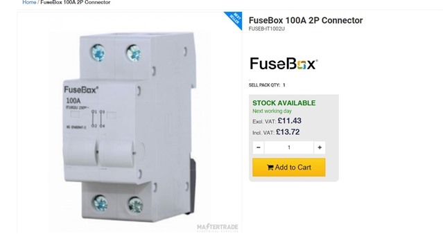
Wondering if in some cases they are a more elegant way of effectively splitting the supply to two consumer units.

Run supply into first unit and then use one of these to connect to the second unit. Struggling to get my head around how I would connect inside the consumer unit and maintain a supply capable of carrying ideally 100 amps.

Presumably the bus bar is ok if the connector is next to the incoming device, second board would use another one of these instead of a switch.

Then presumably use a short internal neutral cable from hager or similar from the neutral bar.

Wondering why I haven't seen others doing something like this. I am mainly looking at EV installs.

I assume these are aimed at when CU's are stacked and enabling effectively internal interconnection, where as for me I would probably have the boards next to each other, maybe with a gap. 

Parents
  • The manufacturer's website (https://fusebox.co.uk) does not make it clear, but it could be used in a double row CU, preferably in series, not parallel. ;-)

  • Couldn't find the product on that site Chris, although well done for finding it, searching for fusebox comes up with allsorts. So haven't seen the data sheet for it.

    I am also struggling to see how this works, apart from as a replacement to a main switch in the second CU.

    Used as a splitter in the first CU, the diagram on the front suggests that the bottom terminals use two prongs of the live busbar, which makes sense since the MCB prongs are usually thinner than the main switch prongs. But they aren't joined within the device (makes sense if used instead of main switch in second CU, L&N separate) so if only one terminal at the top is used for 100A at the second CU, it is fed from one smaller prong on the busbar! It would make sense if both top terminals were used and the cables spliced to go to the second CU, but what would the point be in that?

    Unless fusebox busbar prongs are all the same width each capable of carrying 100A.

Reply
  • Couldn't find the product on that site Chris, although well done for finding it, searching for fusebox comes up with allsorts. So haven't seen the data sheet for it.

    I am also struggling to see how this works, apart from as a replacement to a main switch in the second CU.

    Used as a splitter in the first CU, the diagram on the front suggests that the bottom terminals use two prongs of the live busbar, which makes sense since the MCB prongs are usually thinner than the main switch prongs. But they aren't joined within the device (makes sense if used instead of main switch in second CU, L&N separate) so if only one terminal at the top is used for 100A at the second CU, it is fed from one smaller prong on the busbar! It would make sense if both top terminals were used and the cables spliced to go to the second CU, but what would the point be in that?

    Unless fusebox busbar prongs are all the same width each capable of carrying 100A.

Children
No Data