Star/Delta Isolation Tx For shore supplies

Hi All,

First post so take it easy!

We have a requirement to design an installation using a star/delta isolation transformer to feed shore supply sockets to power and charge new tram/trains (Believe first of their kind in the UK). I am trying to get an understanding of the implications, and what we need to consider in the design as this Tx will be installed within the building supplied from the buildings existing LV system. The trains on board converter has a DC link to ground which could cause earth leakage hence the request for a Star Delta Tx to prevent tripping of the buildings LV supply.  

From my understanding we will need to install insulation monitoring for first fault conditions and on 2nd fault condition will isolate the circuit (An IT System). The train does not require a neutral or CPC (But will we need a CPC to comply with BS7671? If so how does this connect to a delta winding?).  But where I am getting confused is the earthing side of things. Everything within the building including the rails the trains sits on, is bonded back to the building MET. Is there a risk of different potentials within the area? or because they are bonded back to the building MET they will remain at the same potential as this system supplies the Isolation Tx? I may be over thinking this but have never come across this before so eager to educate myself.


Thanks

K

  • Interesting one. You may find that bits of BS7671 do not suit this, for the same reason as it does not suit parts of railway traction installations or mines, or ships. Need to be clear which bits though, as getting an act of parliament through in a hurry just for this job may not be so easy  (as some of those other cases have done )

    It is not clear from the description if the isolation has to be star delta, or if windings that are star to star and just not to distribute the neutral would be equivalent. The advantage is the star centre to earth voltage can be used for fault 1 detection. If not a psuedo neutral must be created for the detection using 3 equal capacitors or resistors or  an additional cunningly wound transformer, but it is extra parts.
    You may not need a CPC on the train, but I presume you intend to detect a cable fault on the secondary side of the TX so some sort of loose earth reference via the fault detection will be needed. Do you have any sort of diagram you can upload, it may be that the mental picture forming in my head is complete tosh!
     Mike

  • Thanks for the reply, it is an interesting one.

    Forget to mention the supplies are 3 Phase and the request for a Delta Secondary Winding is from the manufacturer.

    I cant share any diagrams as such but here's a breakdown of the supply If i have time later on i will sketch out:

    Site Delta/Star 11kV/400v Tx>Main Site Switchboard> Building Switchboard>Proposed Isolation Tx Delta/Delta?>Panel Board> 63A TP Sockets> Plugs into train

    The on board converter is insulated but referred to ground in the DC link intermediate point which could leak currents to earth (This is from the manufacturer), so if the train is supplied via an unearthed delta secondary winding then there should be no tripping but we would need to monitor the cable for faults to earth no so like you said would need some sort of reference? Would this cause an issue on the actual building supply even if we install an Isolation Tx? As everything is bonded back to the building supply which is a standard Delta - Star arrangement?

    Thanks

    K

  • The train does not require a neutral or CPC (But will we need a CPC to comply with BS7671? If so how does this connect to a delta winding?).

    I thought star/delta transformers were normally the other way around - delta on the primary and star on the secondary (at least that's how I understand the DNOs do it). Any wayward earth leakage on the secondary side returns to the secondary star point and so doesn't affect the upstream installation.

    +1 for checking whether BS 7671 is relevant. "Railway traction equipment" is specifically excluded (110.2 (ii)) - but whether a supply used to charge a battery which is then used (at a different moment in time) for traction, does or does not come under that heading,  is I suspect not clear (I can't imagine it was the sort of thing that would have been considered when the words were originally written). That said, the underlying physics and most of the safety principles will be the same regardless of which standard it falls under.

       - Andy.

  • The on board converter is insulated but referred to ground in the DC link intermediate point

    Hmm. Do they mean they connect one side (or the centre tap if bipolar DC ) of the DC bus to the chassis ? that is common for high power inverters and VSDs, but awkward in this case, as then each phase takes it in turn to connect to chassis when it is the most negative of the 3 phases (assuming negative side of the DC is connected to chassis, it could be positive, but usually isn't;) .
    Is so really you want the isolation  transformer in the box  near the convertor, as the cables that supply it have a very different relationship to earth depending if the converter is plugged in or not - unplugged it is IT. plugged it has more of the properties of TN, but as if the N was commutating round the phases visiting each one once per  50Hz cycle.
    A consistent ADS is very hard then as which ever state you design it for the other one looks like a fault.
    I'd be asking for clarity on that.

    Mike

  • please forgive a daft question here. all stray currents must return to their source, so any stray DC should return to the AC/DC converter rather than to the AC source. if the AC/DC converter isolates the DC from the AC, then will there be any stray currents on the AC side (other than the nuisance currents through the earth that we see with all traction)?

  • please forgive a daft question here. all stray currents must return to their source,

    Depends on the nature of  the "source". If it is galvanically isolated from its upstream supply. and has its own "N-PE" link or equivalent, then yes stray currents should return there. But if it's more akin to just a simple bridge rectifier supplied by L & N then the return path would have to involve the N-PE link on the upstream a.c. side.

        - Andy.

  • thanks, Andy. fair point - I guess we need to look a little closer at the details of the installation, but I still suspect that any decent AC/DC converter will provide sufficient isolation to avoid issues of tripping the upstream AC

    Dave

  • I'd not be too sure - I have seen VSD designs where the 3 phases hit 3 diodes up to make a DC bus " B+" and 3 diodes down to a "B-", and there are loads  with an earthed centre tap between B+ and earth, B- and earth., used to create the zero to synthesize the 3 phases coming out to the motor windings by gating pulses from B+ and B- in the right moment.

    Beyond a certain  power level the weight of a 50Hz transformer drives some seemingly odd design decisions, in that it is easier not to isolate but to let things flap about instead. This is part of the problems with car chargers and EMC - a 1:1 transformer at 50Hz is not a practical object for the boot of a small car at the power levels needed for fast charge..There should be room in a train, but I'm not sure if it would be designed that way or not.

    Mike

  • thanks, gents. I know it's the last resort of the desperate engineer, but do we need to get the drawings out? Dave

  • Thanks All for the replies.

    Forgive my lack of knowledge on the Electronics/DC side of things, looks like I have some reading to do.

    The purpose of the isolation Tx is to prevent any leakage current from coming onto the existing LV services at the building, typically we were looking to follow the network rail standard (This isnt a network rail project) which uses a delta/star Tx with a 2.4kOhm resistor at the star point to limit the earth fault current, this allowed for enough fault current to trip protective devices. We suggested this but the manufacturer of the converter recommended that a 100kOhm resistor is used or a Delta secondary winding ungrounded. We feel that using a 100kOhm resistor and monitoring the faults at such a low level would likely cause nuisance alarms or trips.

    Using a Delta secondary we feel we would need some sort of earth reference to protect the swa cabling if it were to come into contact with a line conductor, to do this surely we would need an earthing transformer in addition to the Iso Tx which is basically a star wound Tx? I think what I am asking is how would you supply a 63A TP Socket from a Delta Secondary winding of a Tx?

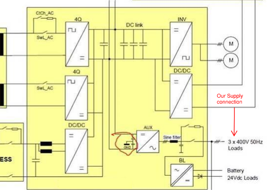
    Below is a diagram of the converter (Circled is the DC link grnd), the manufacturer has said the following "the infrastructure ground and the rail ground are on the same potential. The high frequency current will flow back to the midpoint of the DC-link (connection between sine filter and capacitor bank mid points)" which I read as what Dave mentioned above. The site exposed and extraneous conductive parts including rails are all bonded back to the MET so would be at the same potential.

    Appreciate the replies

    K