Star/Delta Isolation Tx For shore supplies

Hi All,

First post so take it easy!

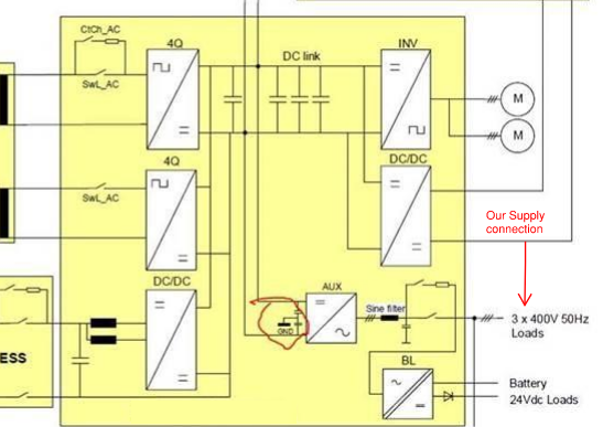
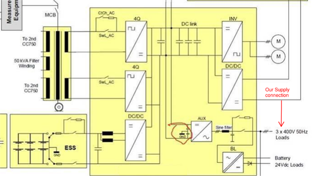
We have a requirement to design an installation using a star/delta isolation transformer to feed shore supply sockets to power and charge new tram/trains (Believe first of their kind in the UK). I am trying to get an understanding of the implications, and what we need to consider in the design as this Tx will be installed within the building supplied from the buildings existing LV system. The trains on board converter has a DC link to ground which could cause earth leakage hence the request for a Star Delta Tx to prevent tripping of the buildings LV supply.  

From my understanding we will need to install insulation monitoring for first fault conditions and on 2nd fault condition will isolate the circuit (An IT System). The train does not require a neutral or CPC (But will we need a CPC to comply with BS7671? If so how does this connect to a delta winding?).  But where I am getting confused is the earthing side of things. Everything within the building including the rails the trains sits on, is bonded back to the building MET. Is there a risk of different potentials within the area? or because they are bonded back to the building MET they will remain at the same potential as this system supplies the Isolation Tx? I may be over thinking this but have never come across this before so eager to educate myself.


Thanks

K

Parents
  • Thanks All for the replies.

    Forgive my lack of knowledge on the Electronics/DC side of things, looks like I have some reading to do.

    The purpose of the isolation Tx is to prevent any leakage current from coming onto the existing LV services at the building, typically we were looking to follow the network rail standard (This isnt a network rail project) which uses a delta/star Tx with a 2.4kOhm resistor at the star point to limit the earth fault current, this allowed for enough fault current to trip protective devices. We suggested this but the manufacturer of the converter recommended that a 100kOhm resistor is used or a Delta secondary winding ungrounded. We feel that using a 100kOhm resistor and monitoring the faults at such a low level would likely cause nuisance alarms or trips.

    Using a Delta secondary we feel we would need some sort of earth reference to protect the swa cabling if it were to come into contact with a line conductor, to do this surely we would need an earthing transformer in addition to the Iso Tx which is basically a star wound Tx? I think what I am asking is how would you supply a 63A TP Socket from a Delta Secondary winding of a Tx?

    Below is a diagram of the converter (Circled is the DC link grnd), the manufacturer has said the following "the infrastructure ground and the rail ground are on the same potential. The high frequency current will flow back to the midpoint of the DC-link (connection between sine filter and capacitor bank mid points)" which I read as what Dave mentioned above. The site exposed and extraneous conductive parts including rails are all bonded back to the MET so would be at the same potential.

    Appreciate the replies

    K

  • OK the '4q' are a bridge, but probably not of diodes, but of devices such as IGBTs or power FETs that can be thought of as switches that get opened or shut at the right part of the wave form to turn the AC into DC, and allow the tank capacitors on the DC bus to be filled to a pre- determined target voltage.

    However, just like a diode bridge, but with a bit more finesse, either end of  the DC bus capacitors may be connected to either (or sometimes none) of the incoming lines at different parts of the cycle.

    The earth is indeed sort of loosely attached to the centre of that capacitance, but the good news is that is not a load carrying connection.

    To the LHS are two black bars that look like Tx windings but this is not 3 phase - what else is happening to the left and which of these lines is cut by the plug and socket ?
    Mike.

Reply
  • OK the '4q' are a bridge, but probably not of diodes, but of devices such as IGBTs or power FETs that can be thought of as switches that get opened or shut at the right part of the wave form to turn the AC into DC, and allow the tank capacitors on the DC bus to be filled to a pre- determined target voltage.

    However, just like a diode bridge, but with a bit more finesse, either end of  the DC bus capacitors may be connected to either (or sometimes none) of the incoming lines at different parts of the cycle.

    The earth is indeed sort of loosely attached to the centre of that capacitance, but the good news is that is not a load carrying connection.

    To the LHS are two black bars that look like Tx windings but this is not 3 phase - what else is happening to the left and which of these lines is cut by the plug and socket ?
    Mike.

Children
  • Traction supplies are sometimes two-phase (but 90 deg apart & not 120 deg) as supplied by a SCOTT transformer.

    Is this the intended input to this converter?

    (I believe the scott arrangement is used so that, with a conventional track layout each of the 'up' & 'down' running lines can be fed from a different 'phase' but still present a kind-of-balanced load to a 3 phase supply).

  • The section on left shows the 25kv role connection which is disconnected once train enters the maintenance building and then gets plugged into the shore supply to power the train and charge batteries whilst it is being maintained. 

    For me I'm looking at supplying this plug based on manufacturers requirements train is already built so can't change that). 

    They require a 3 phases only as said before via a delta secondary winding of a isolation tx,  we are also using a pilot pin and an interlocking circuit (don't want the train pulling off when it is still plugged in!)

  • Able you able to show us the next 'block' to the immediate left of the block diagram you have provided? (ie. the one that is semi cut off) This might be a scott three phase to two phase transformer...... in which case things make a bit more sense.

  • Indeed picture is below

    As I mentioned before it is the shore supply Im having trouble with as the industry standard we would normally install is not compatible with this?

  • Note* Ignore the Our supply connection red note on the drawing

  • thanks, Kieron. Is the shore supply 25kV AC supply to the primary winding of the main transformer, or some lower voltage on the secondary windings to the two 4Q controlled rectifiers, or something else, please? Dave

  • The shore supply is 400v 3P which is to be fed from the onsite LV infrastructure. Separate from the the 25kV I believe.

    It is used to power auxiliary circuits and provide a charge to the battery.

    I'm looking at how we supply this without affecting the on site lv via the dc current leakage, which is why a isolation transformer was proposed but don't quite understand how we do this with a delta/delta tx fed from the building then supplies a panel board with the outgoing circuits to the shore supplies.

    K

  • thanks, Keiron. how's that 400V supply connected into the circuit which you've shared with us, please? Dave