Cable size of tails supplying a CU

I have a temporary CU board setup for rewires etc. (CU, isolator, 25mm tails, earth block, socket outlets) that I want to make smaller (and also want to know theses answers anyway).

If I made a new temporary CU board setup with a mains isolator to 4mm T&E tails, to single module 32A RCBO, to 4mm T&E final circuit cable, to a socket outlet or two, do you think the 4mm tails would be compliant?

Overload protection - The 4mm tails (and reduction in CCC) are protected from overload by the 32A RCBO and design current of 32A of the socket circuit.

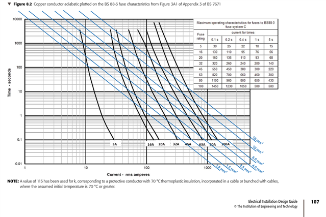
Fault protection - Lets say most common main fuse in domestic is 100A (worst case) BS 1361 / BS 88-3 which has a max Zs of 0.27 ohms to achieve a 5 second disconnection time for a distribution circuit on a TN system (0.14 ohms for 0.4 seconds). So if the Zs is <0.27 it's OK.

Main (tails) earth size would need to be the same as the line conductor (4mm) to comply with table 54.7.

Or use the adiabatic equation (amusing a Zs of less than 0.27 ohms):

S =
√ I2 x t
/ k

Where:

Zs = 0.27 ohms
I (fault current) = 851A (230 / 0.27)
t = 1s (850A on BS 88-3 time current graph)
k = 115 (70* thermoplastic) or 143 if separate cable

√ 851 x 851 x 1 = 851
851 / 115 = 7.4mm2
or 851 / 143 = 5.9mm2 (if separate cable)

So 4mm supply tails with 4mm earth using table 54.7 would be adequate? Am I missing anything? Thanks.

Parents
  • You can't take the loop impedance at one point on the circuit only ... you need to consider fault currents along the whole length.

    Best place to look as to how to do this properly is Section 8.6 of the IET Electrical Installation Design Guide. For fuses, you plot t=k2S2/I2 for the conductor size you want to check, on the tripping characteristic curve in Appendix 3 of BS &671, which always comes out as a line on that graph-paper:

    The results for 70 degree PVC cables with copper conductors when using a BS 88-3 fuse are shown in Table 8.10 of the EIDG. For a 100 A BS 88-3 fuse, fault current, needs to exceed:

    • 1100 A to protect 4 sq mm cpc/line conductor (copper, 70 deg PVC)
    • 1000 A to protect 6 sq mm cpc/line conductor(copper, 70 deg PVC)
    • 600 A to protect 10 sq mm cpc/line conductor (copper, 70 deg PVC)
    • 440 A to protect 16 sq mm cpc/line conductor (copper, 70 deg PVC)

    So, for your example of prospective fault current (at the origin) of 850 A, you'd need 10 sq mm cable minimum ... but you can also see in the general case why the recommended approach is use 16 sq mm for the earthing conductor in TN supplies.

    4 sq mm will definitely not do the trick in all installations (you'd need at least 1100 A at all points up to the 32 A breaker) ... between the 100 A fuse and the CU - if there is a fault it might well cook.

Reply
  • You can't take the loop impedance at one point on the circuit only ... you need to consider fault currents along the whole length.

    Best place to look as to how to do this properly is Section 8.6 of the IET Electrical Installation Design Guide. For fuses, you plot t=k2S2/I2 for the conductor size you want to check, on the tripping characteristic curve in Appendix 3 of BS &671, which always comes out as a line on that graph-paper:

    The results for 70 degree PVC cables with copper conductors when using a BS 88-3 fuse are shown in Table 8.10 of the EIDG. For a 100 A BS 88-3 fuse, fault current, needs to exceed:

    • 1100 A to protect 4 sq mm cpc/line conductor (copper, 70 deg PVC)
    • 1000 A to protect 6 sq mm cpc/line conductor(copper, 70 deg PVC)
    • 600 A to protect 10 sq mm cpc/line conductor (copper, 70 deg PVC)
    • 440 A to protect 16 sq mm cpc/line conductor (copper, 70 deg PVC)

    So, for your example of prospective fault current (at the origin) of 850 A, you'd need 10 sq mm cable minimum ... but you can also see in the general case why the recommended approach is use 16 sq mm for the earthing conductor in TN supplies.

    4 sq mm will definitely not do the trick in all installations (you'd need at least 1100 A at all points up to the 32 A breaker) ... between the 100 A fuse and the CU - if there is a fault it might well cook.

Children
  • Thanks for the help

  • When you say about not taking the Zs from one point, the furthest (most onerous / resistance) point is used to solve this isn't it?

    I'm trying to get my head around this chart but I'm confused. Isn't the purpose of the adiabatic equation to find the minimum size of cable that can be used to prevent the limiting temperature of the cable insulation is reached (70*C) during fault current for the particular fuse type and rating? So in my calculation that was 7.4mm2 or 5.9mm2 depending on the k factor. What's the purpose of the Zs and adiabatic crossover chart?

  • For a 100 A BS 88-3 fuse, fault current, needs to exceed:

    • 1100 A to protect 4 sq mm cpc/line conductor (copper, 70 deg PVC)
    • 1000 A to protect 6 sq mm cpc/line conductor(copper, 70 deg PVC)
    • 600 A to protect 10 sq mm cpc/line conductor (copper, 70 deg PVC)
    • 440 A to protect 16 sq mm cpc/line conductor (copper, 70 deg PVC)

    That is confusing and seems rather counter-intuitive! However, am I right in thinking that with 4 sq mm cable, the fault current must be at least 1100 A so that the fuse blows before the cable can overheat? The 6 sq mm cable can absorb more energy so it can afford to wait slightly longer for the fuse to blow, etc.

  • I wondered whether Graham or anybody else would like to comment please?

  • Happy to comment ;-0 Folk can then point out the erroneous bits and we can converge on a more accurate description of what is going on.. If the loop impedance is increased, the fuse takes longer to blow and the 'really fast, adiabatic, constant energy I2t = constant' assumption breaks down. Actually, in extremis by time the PSSC is less than about  1,5 times the fuse rating, the heat arriving and leaving balance and the fuse wire reaches an equilibrium after several minutes but at temperature that may well be below its melting point of nearly 1000C, and that current flows forever, and the element within the fuse never blows - you just get a hot fuse and holder.

    A similar thing happens to the calculation for wire damage, wire - but, and this may be important, because the permitted temperature rise is much less - we are browning off and embrittling the insulation, usually setting a danger limit , between 160 and 220C, nothing like  approaching the melting point of copper, the shape of the safe area of the I/T curve has a different aspect ratio. Also for 4mm copper the fuse highest no blow current exceeds the cable damage level. So, at low PSSC the cable is at risk, but at high ones it is not.

    I agree it feels odd. If the cable is  at risk, (and if you care), also depends on other factors, the big one being the average load prior to the fault, which may pre heat the cable or not, and if damage is likely to go un-noticed.

    Of course real faults are pretty much never  zero resistance - if they were there would be no heat, light or sound - there usually is so the fault has some voltage drop, but we will leave that dog asleep I think.

    Mike.

  • Or to put it another way, as the fault current increases not only does the opening of the fuse get faster, the speed of opening accelerates such that I²t actually declines. Which is why all the old text books only considered max Zs as being the worst case (not true with MCBs now of course, where you might have to consider faults near the start of the circuit as giving the highest I²t and at the end of the circuit for the worst disconnection time).

        - Andy.

  • I wondered whether Graham or anybody else would like to comment please?

    Apologies   I missed this as it was embedded in a thread.

    Yes, I think you've got it.

    It does look counter-intuitive, but it's because the fuse acts a lot faster with more current - the fuse heats up a lot faster than the cable really.

    The best way to look at this is on the line plot, so the [non-adiabatic] energy factor the cable can absorb is k2S2, and what is plotted on the time-current curves is t=k2S2/I2. Luckily, we don't need to actually calculate for smaller installations up to 100 A single-phase, as there are Tables in the OSG that already have the information.

    With circuit-breakers, the same logic may not always hold, particularly in the 'instantaneous' (<0.1 s) region that we are normally operating in for BS 7671 disconnection times - and large current faults L-N. Hence, BS 7671 telling you to use the value of I2t (let-through energy) quoted by the manufacturer (or the standard) for circuit-breakers ... and so for circuit-breakers, we don't consider the actual fault currents involved at all, but calculate Smin=√([I2t]/k), where [I2t] is the let-through energy quoted by the manufacturer (or product standard).

  • Yes, I think you've got it.

    Graham, thank you - that is reassuring. :-)