Cable size of tails supplying a CU

I have a temporary CU board setup for rewires etc. (CU, isolator, 25mm tails, earth block, socket outlets) that I want to make smaller (and also want to know theses answers anyway).

If I made a new temporary CU board setup with a mains isolator to 4mm T&E tails, to single module 32A RCBO, to 4mm T&E final circuit cable, to a socket outlet or two, do you think the 4mm tails would be compliant?

Overload protection - The 4mm tails (and reduction in CCC) are protected from overload by the 32A RCBO and design current of 32A of the socket circuit.

Fault protection - Lets say most common main fuse in domestic is 100A (worst case) BS 1361 / BS 88-3 which has a max Zs of 0.27 ohms to achieve a 5 second disconnection time for a distribution circuit on a TN system (0.14 ohms for 0.4 seconds). So if the Zs is <0.27 it's OK.

Main (tails) earth size would need to be the same as the line conductor (4mm) to comply with table 54.7.

Or use the adiabatic equation (amusing a Zs of less than 0.27 ohms):

S =
√ I2 x t
/ k

Where:

Zs = 0.27 ohms
I (fault current) = 851A (230 / 0.27)
t = 1s (850A on BS 88-3 time current graph)
k = 115 (70* thermoplastic) or 143 if separate cable

√ 851 x 851 x 1 = 851
851 / 115 = 7.4mm2
or 851 / 143 = 5.9mm2 (if separate cable)

So 4mm supply tails with 4mm earth using table 54.7 would be adequate? Am I missing anything? Thanks.
  • you will need to think how you get the 4mm T and E into the meter tails without having a short length of single insulated exposed  somewhere, though in practice it is not a great risk. The  thinking in terms of Zs and ADS is OK, your adiabatic calc suggests the cable may be cooked during a fault, though a fault will probably involve cable replacement anyway.  This works as long as your new 'tail' is not long enough to actually affect the PSSC. Id be aiming for an in-line box andd smaller fuse or MCB if it was more than a few metres.  Personally I might have used flexible rubber type  cable rather than TnE for this, as the whole set up is always going to be on the move.

    It may raise a few eyebrows, but I cannot see any technical objection to the idea.

    Mike,

  • You can't take the loop impedance at one point on the circuit only ... you need to consider fault currents along the whole length.

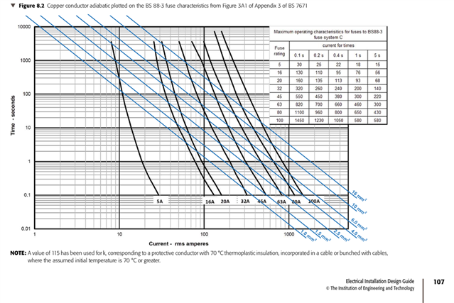
    Best place to look as to how to do this properly is Section 8.6 of the IET Electrical Installation Design Guide. For fuses, you plot t=k2S2/I2 for the conductor size you want to check, on the tripping characteristic curve in Appendix 3 of BS &671, which always comes out as a line on that graph-paper:

    The results for 70 degree PVC cables with copper conductors when using a BS 88-3 fuse are shown in Table 8.10 of the EIDG. For a 100 A BS 88-3 fuse, fault current, needs to exceed:

    • 1100 A to protect 4 sq mm cpc/line conductor (copper, 70 deg PVC)
    • 1000 A to protect 6 sq mm cpc/line conductor(copper, 70 deg PVC)
    • 600 A to protect 10 sq mm cpc/line conductor (copper, 70 deg PVC)
    • 440 A to protect 16 sq mm cpc/line conductor (copper, 70 deg PVC)

    So, for your example of prospective fault current (at the origin) of 850 A, you'd need 10 sq mm cable minimum ... but you can also see in the general case why the recommended approach is use 16 sq mm for the earthing conductor in TN supplies.

    4 sq mm will definitely not do the trick in all installations (you'd need at least 1100 A at all points up to the 32 A breaker) ... between the 100 A fuse and the CU - if there is a fault it might well cook.

  • Thanks for the help

  • Thanks for the help, Mike

  • What are you doing for (temporary) main bonding? If that's going through your CU's earthbar, then your "c.p.c." will have to function as a main bonding conductor as well - so likely a 10mm² minimum even if the live tails can be smaller. Omitting main bonding might press local c.p.c.s (e.g. to boiler) into being bonding conductors, which probably isn't a solution if the incoming services are still metallic.

       - Andy.

  • 851 / 115 = 7.4mm2
    or 851 / 143 = 5.9mm2 (if separate cable)

    So 4mm supply tails with 4mm earth using table 54.7 would be adequate?

    I think you worked that out yourself! Your calculation shows you'd need at least 7.4mm² (multicore) or 5.9mm² (separate) to comply - so 4mm² is too thin on those assumptions.

       - Andy.

  • 5.9mm² (separate) to comply

    Only if physically separate so the assumption of initial temperature of 30 deg C (Table 54.2) is valid, i.e. cable is not heated by being close to (tiewrapped, bunched, etc.) the live conductors. Note that Table 54.3 says 'or bunched with cables'

  • Good shout. There's an earth block that I connect the existing bonding and earth to.

  • That's using table 54.7 instead, but yeah the calculation says bigger

  • When you say about not taking the Zs from one point, the furthest (most onerous / resistance) point is used to solve this isn't it?

    I'm trying to get my head around this chart but I'm confused. Isn't the purpose of the adiabatic equation to find the minimum size of cable that can be used to prevent the limiting temperature of the cable insulation is reached (70*C) during fault current for the particular fuse type and rating? So in my calculation that was 7.4mm2 or 5.9mm2 depending on the k factor. What's the purpose of the Zs and adiabatic crossover chart?