This discussion is locked.
You cannot post a reply to this discussion. If you have a question start a new discussion

RCD testing for additional protection

Hi all, im trying to get my head round this question if anyone can help. Amendment 2 no longer requires us to record  RCD x5 results; I understand this is due to manufacturers of type A RCD's utilising various test currents to achieve disconnection times, and that due to some meters not operating at these specific test currents many were returned as defective when they were okay, and it was the testing method at fault.

In the old 18th ed x5 tests operating within 0.04 s used to be recognised in an AC system (as well as other methods such as bonding ect) as providing additional protection. However, because we no longer need to verify this test, how can we be sure the RCD will offer this additional protection ?? The x1 test may fulfil the disconnection time of 0.4s for a TN system for example, but this test verif'ys fault protection only does it not ?. As an RCD is generally used for additional protection (in a domestic sense at least) then how can we be sure it offers additional protection without the x5 test ?

I realise the x5 tests on type A RCD's pose problems as mentioned above. Has it been decided then that if a 30mA RCD passes the x1 test then its more than likely to pass the x5 as well and so no need to verify ??  I cannot find a definite answer to this !

  • Ignoring for the moment the politics of watering down the testing rules, I think you may have missed something, so apologies if the next paragraph is a bit 'I knew that'

    There are two situations an RCD operates -

    A metallic fault path via the CPC, that probably has a lot more current than 30ma or 150mA - so a test at almost any current will assure the suitability for that purpose. Here the problem is the touch voltaeg present on the exposed 'earthed' metalwork while the fault current is passing - if the CPC path and the live are the same resistance (TN assumption) then the exposed voltage will be around 120V, and ADS that operates within half a heartbeat (taken as 0,4 seconds) is OK for the protection of human life.

    for TT the voltage jump is more like 200V, and that assumed safe disconnection time falls to 0,2 seconds

    Considerably slower would be fine for protection against fire, but except for submains, this is not normally the  condition we care about.

    The second class is where the human is in the loop - the classic barefeet on the grass, damaged  lawnmower flex in hand (ignoring the non-electrical foolishness of using a lawn mower in bare feet).

    This case tests the RCD, as the current you are supposed to be able to tolerate for a long period is less than 30mA, and so there is no need to to disconnect at anything less than 30mA , but a real RCD  may knock off at not a lot above 15-20. The body resistance will be very variable, from tens of k ohms to hundreds of ohms, depending on contact area, sweat, and of course the current will depend on this and the rest of the current path - paving slabs or puddle are very different.


    A modern A type RCD must still be capable of passing any test that a compliant  AC type would have passed, and in addition has its behaviour better defined for some un-smoothed DC conditions as well, where an AC may act up.
    Now my understanding is that the makers say if it passes at the higher current, then that's OK, and at one point it looked like test at 5 times only was going to be the reccomendation in the standards now reflect this. But there is no technical reason not to test at 30mA, and if you do , you should expect it to trip, promptly. After all, this is the only safety of life case.
    So the new requirement is a bit of a kludge to fit all cases.

    Regardless of RCD type, e.g. AC, A, F or B, an alternating current test shall be used at the rated residual operating current (IΔn), with a maximum operating time not exceeding 300 ms for general non-delay type RCDs.

    The assumption is that a shock of this duration is safe, and in most cases, the device will speed up as the fault impedance falls, and usually will be a lot faster.

    Certainly, most of the modern ones that have touched my meter in the last few years have either been dead, and not tripped at any current, or have fired off within a few 10s of msec at 30mA.

    Mike.

  • I still do both. It is probably easier to let my MFT do its stuff on auto than to omit the 5 x tests and do the rest manually. And if you have done the tests, you might as well put them on the certificate or report.

  • However, because we no longer need to verify this test, how can we be sure the RCD will offer this additional protection ??

    How do we verify that an MCB will trip or a fuse open for ADS? We don't test individual tests on site, but rely on the specification & manufacturer. RCDs are somewhat less reliable, but generally either they work OK or they don't - it's pretty unlikely that it would pass the x1 test but fail a 5x one (most of the time a 1x test comes in below 40ms anyway). At one point in the debate, some manufacturers were asking us to forget about RCD test meters altogether and just use the T button.

       - Andy.

  • Thanks for the responses, what I deduce from them is -- if an 30mA RCD operates within 300 ms of a fault on a TN system then it satisfies the 0.4 second disconnection and touch voltage limits; a higher fault current would operate the RCD more quickly and therefore there is no need to test at a higher current. Does that sound right.

    @ Chris Pearsson, Carrying out the range of tests on the auto function might sound easier but may not provide a suitable value on the x5 test  (if your expecting below 40 ms) due to different manufacturers having differing x5 perameters; this is certainly the case for RCD's other than type AC, and the reason why the regs have changed to exclude x5 tests. And why I asked the question.

    @ aajewsbury, yes that is logical, it just doesn't immediately appear like a improved way of verifying a device by omitting a test. As you say we rely on MCB's without testing so why not rely on just 1 test (at both phase angles) for an RCD.

    Just to note that m not opposed to the changes and deletion of the x5 test, its just I couldn't get my head around why the test was omitted, but now I know why (I hope).

  • Ive another question!! or to put it another way its the same question but a different way of asking !

    In the 18th ed (2018) what were the principles that recognised tripping times of <40ms on a x5 test provided additional protection. How did they arrive at that ?

  • In the 18th ed (2018) what were the principles that recognised tripping times of <40ms on a x5 test provided additional protection. How did they arrive at that ?

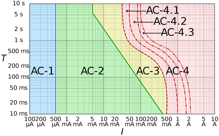
    Most shock protection approaches is derived from a chart like this (from an IEC standard) - which plots the effect electric current on a representative human:

    The blue AC-1 region indicates no effect, AC-2 can be felt but mostly does no harm, AC-3 is muscle contraction and AC-4 covers ventricular fibrillation (which tends to lead to death pretty rapidly). As you can see the effect depends both on duration as well as current. So things are arranged to try and keep the victim out of AC-3 and certainly outside of AC-4.

    (There's a similar one for direct current, where the regions are labelled DC-)

    When it comes to ADS we don't directly know the current that might flow though a victim, but we do know the likely touch voltage - so with a educated guess that body resistance would likely be at least 1kΩ - you can then read Volts instead of mA along the x-axis. For TN systems (where the line conductor and c.p.c. have similar impedances) the touch voltage would be around half the line voltage (115V ish) while on TT systems (where the c.p.c. side of the loop can have a very much higher impedance due to having to pass through Earth electrodes) the touch voltage may well be much closer to the full line voltage (230V) - so you might also see where the 0.4 and 0.2s disconnection times come from.

        - Andy.

  • It comes back to testing the metallic fault path versus human in the loop. It is of course impossible  to make a device that trips never at 29,99mA and yet trips at full speed at 30mA, so tests were derived in a way that mimicked the behaviour of a typical device of the time, where the imbalance in the sense windings drove the actuator, so lower fault current > slower operation, and somewhere below 30mA no operation at all.

    The modern way is to use some electronics to look at the voltage on the sense winding, and compare  it with a preset threshold. if it exceeds it at all, then a triac or SCR fires and the mains voltage L-N is used to operate the firing mechanism with a force that is independent of the fault magnitude, and has everything to do with the mains voltage. 

    So trip times in a modern device are essentially constant above threshold,* and less prone to jam due to corrosion or grease stiction.

    It does mean that this kind of newer device does not work properly if the neutral is interrupted  or the supply voltage is low on the supply side.

    Mike.

    * some very new and even fancier ones fake delay in inverse proportion to fault current, but it is not a mechanical thing but an electronic integration to achieve a similar end, and  reduce false alarm tripping

  • @ Chris Pearsson, Carrying out the range of tests on the auto function might sound easier but may not provide a suitable value on the x5 test  (if your expecting below 40 ms) due to different manufacturers having differing x5 perameters; this is certainly the case for RCD's other than type AC, and the reason why the regs have changed to exclude x5 tests. And why I asked the question.

    First make sure that your MFT is set to type AC, or A, or WHY.

    Of course if, for some reason, an RCD passed the x1 test, but not x5, you have made life difficult for yourself.

  • I was led to believe the omission of  x5 tests from am2 was due to the certain types of  RCD not responding to x5 tests in under 40ms due to the manufacturers design. x5 test parameters of certain types of RCD can be different according to manufacturer (Hager type A RCDs were a case in point); these different test parameters of the manufacturers were at odds with some standard UK meters which led to the return of many RCD's to the manufacturers as defective when in fact they were okay, and it was the testing method at fault. I mean why omit the x5 test if its not an issue (which it is and is why they omitted it). Generally most electricians cannot afford the newest meter that performs all these tests for each different manufacturer. Just saying, might be wrong thou as its a tricky subject