This discussion is locked.
You cannot post a reply to this discussion. If you have a question start a new discussion

RCD testing for additional protection

Hi all, im trying to get my head round this question if anyone can help. Amendment 2 no longer requires us to record  RCD x5 results; I understand this is due to manufacturers of type A RCD's utilising various test currents to achieve disconnection times, and that due to some meters not operating at these specific test currents many were returned as defective when they were okay, and it was the testing method at fault.

In the old 18th ed x5 tests operating within 0.04 s used to be recognised in an AC system (as well as other methods such as bonding ect) as providing additional protection. However, because we no longer need to verify this test, how can we be sure the RCD will offer this additional protection ?? The x1 test may fulfil the disconnection time of 0.4s for a TN system for example, but this test verif'ys fault protection only does it not ?. As an RCD is generally used for additional protection (in a domestic sense at least) then how can we be sure it offers additional protection without the x5 test ?

I realise the x5 tests on type A RCD's pose problems as mentioned above. Has it been decided then that if a 30mA RCD passes the x1 test then its more than likely to pass the x5 as well and so no need to verify ??  I cannot find a definite answer to this !

Parents
  • In the 18th ed (2018) what were the principles that recognised tripping times of <40ms on a x5 test provided additional protection. How did they arrive at that ?

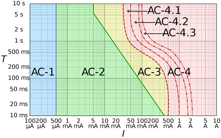
    Most shock protection approaches is derived from a chart like this (from an IEC standard) - which plots the effect electric current on a representative human:

    The blue AC-1 region indicates no effect, AC-2 can be felt but mostly does no harm, AC-3 is muscle contraction and AC-4 covers ventricular fibrillation (which tends to lead to death pretty rapidly). As you can see the effect depends both on duration as well as current. So things are arranged to try and keep the victim out of AC-3 and certainly outside of AC-4.

    (There's a similar one for direct current, where the regions are labelled DC-)

    When it comes to ADS we don't directly know the current that might flow though a victim, but we do know the likely touch voltage - so with a educated guess that body resistance would likely be at least 1kΩ - you can then read Volts instead of mA along the x-axis. For TN systems (where the line conductor and c.p.c. have similar impedances) the touch voltage would be around half the line voltage (115V ish) while on TT systems (where the c.p.c. side of the loop can have a very much higher impedance due to having to pass through Earth electrodes) the touch voltage may well be much closer to the full line voltage (230V) - so you might also see where the 0.4 and 0.2s disconnection times come from.

        - Andy.

Reply
  • In the 18th ed (2018) what were the principles that recognised tripping times of <40ms on a x5 test provided additional protection. How did they arrive at that ?

    Most shock protection approaches is derived from a chart like this (from an IEC standard) - which plots the effect electric current on a representative human:

    The blue AC-1 region indicates no effect, AC-2 can be felt but mostly does no harm, AC-3 is muscle contraction and AC-4 covers ventricular fibrillation (which tends to lead to death pretty rapidly). As you can see the effect depends both on duration as well as current. So things are arranged to try and keep the victim out of AC-3 and certainly outside of AC-4.

    (There's a similar one for direct current, where the regions are labelled DC-)

    When it comes to ADS we don't directly know the current that might flow though a victim, but we do know the likely touch voltage - so with a educated guess that body resistance would likely be at least 1kΩ - you can then read Volts instead of mA along the x-axis. For TN systems (where the line conductor and c.p.c. have similar impedances) the touch voltage would be around half the line voltage (115V ish) while on TT systems (where the c.p.c. side of the loop can have a very much higher impedance due to having to pass through Earth electrodes) the touch voltage may well be much closer to the full line voltage (230V) - so you might also see where the 0.4 and 0.2s disconnection times come from.

        - Andy.

Children
No Data