Open PEN detection for 722.411.4.1 (iv) - Part 2

Following on from from the discussion  Open PEN detection for 722.411.4.1 (iv) -  and the various discussions about uncleared TT earth faults and similar causing the substation earth reference to wander about, I've been thinking (bad idea I know, but...) and there's something that's been troubling me. Maybe someone can reassure me.

These open-pen devices (for the (iv) option) work by measuring the L-N voltage, and using that to approximate the voltage difference between N/PE/PEN and true earth. Previously we discussed how the nature of the 3-phase connected loads (either 3-phase loads or combinations of single phase loads) could cause the severed N to wander about the place - and not all the combinations where it was more than 70V away from true earth would be detected by the L-N voltage monitoring.  We had this (phasor) diagram:

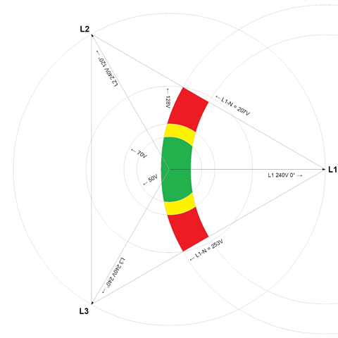
(Green was the bit where the device remains connected with touch voltages <50V, yellow where it remains connected despite touch voltages >50V and red >70V)

So, I think, in effect the monitor is effectively using the substation's earth electrode as its reference for true Earth, offset by the line voltage, but still ultimately referenced to the substation's electrode. In the above diagram the substation's Earth is the centre point.

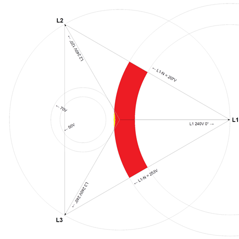
So I now add in the other thought - say we had some current returning to the substation's star point via the general mass of the earth. Probably quite likely in an Open-PEN situation, especially where there are still a few true extraneous-conductive-parts about, or someone's up with the latest version of BS 7671 and installed an additional electrode on their PME installation. We'd then create a p.d. across the soil surrounding the substation's electrode(s). Exact values would vary tremendously, as substation electrode resistance values could be anything from well below 1Ω to nearly 20Ω. For the sake of illustration say we had a substation electrode say 2Ω and 20A of return current - V=IR so our substation star point would be offset by 40V from true Earth. The phase angle of the return current would depend on the mix of loads across the 3 phases - but for the sake of argument (and because it makes the diagrams a bit simpler to draw) lets say it's in phase with the line our charger is on. So "0v" at the substation is really 40V and L1's "240V" is really 280V (similarly the other two phases will be offset, but by odd angles which makes calculating the exact values tiresome). We still have the normal 230/400V nominal relationship between conductors, but they're all offset from Earth by that 40V.

In a simple single phase system the additional resistance on the broken N but now through the general mass of the earth would severely limit the current that could flow through the loads, so the voltage across the loads would collapse, almost certainly pushing the open-PEN device to trip. But with a 3-phase supply I'm thinking that the bulk of the load currents is supplied between lines - from one line, via "artificial star point" of the far end of the broken PEN to the other lines, so isn't limited by the ground resistance, and so voltages across loads is likely to hold up fairly well - the ground resistance only affecting the N current, resulting from the imbalance of the loads, which may be small in comparison to the load currents, so only have a small effect on the voltage on the load end of the severed PEN conductor.

 So now the true earth point is 40V to the left of the centre of our 3-phase triangle, which I think means the open-PEN device is even more likely to mos-interpret unsafe touch voltages as acceptable.

... so have I gone wrong somewhere?

      - Andy.

Parents
  • Something else to consider - your diagram is showing a single electrode connected to the star point of the transformer - it would be very unusual for there to be only the single electrode connected to the star point/PEN - perhaps a reason why PNB is limited to 4 customers? in PME installations, there would likely be a number of LV PEN conductors connected to the star point, so on a break in one PEN conductor, there are lots of return path earth electrodes.

    Yes, although I did indicate a lower resistance than is likely from a single rod. If you consider a single phase situation the transformer winding is kicking out something in the region 250V and in a broken PEN situation that will be divided between the connected load, connections to earth on the far side of the PEN break and connections to earth on the supply side of the break (ignoring v.d. along the line and PEN conductors as a first approximation). The offset of the star point at the substation depends more on the balance between those three impedances rather than any absolute value. If on the load side of the break, additional PME electrodes would be more of a hindrance than a help in terms of keeping the star point close to 0V. With loads across 3-phases downstream of the break it gets more complicated to analyse - the current through the ground will be the normal N current (resulting from the imbalance of the loads, rather than controlled directly by the loads themselves) and limited by the impedance of connections to ground on the load side of the break, but still the substation's star point is going to be offset by the product of the impedance of the earth connections on supply side of the break and the N current - and my gut feel is that even quite reasonable numbers quite rapidly give worrying results. The chances might be small, but as it's the very circumstances that we're relying on open-PEN devices to operate correctly in.

    I suspect the in quite a few (non-urban) situations the source electrodes might have a relatively high impedance - I'm thinking of  a typical village setup - decent sized 3-phase transformer on poles behind the pub, separate LV and HV earthing systems, and a mix of ABC overheads and underground distribution and maybe a steel framed commercial/industrial building or two as well. All we can say for sure is that the transformer's LV electrode should be <20Ω and any additional electrodes might be significantly higher than that (as there's no specific limit specified) - overall we're still likely to be looking at several Ohms.

       - Andy.

Reply
  • Something else to consider - your diagram is showing a single electrode connected to the star point of the transformer - it would be very unusual for there to be only the single electrode connected to the star point/PEN - perhaps a reason why PNB is limited to 4 customers? in PME installations, there would likely be a number of LV PEN conductors connected to the star point, so on a break in one PEN conductor, there are lots of return path earth electrodes.

    Yes, although I did indicate a lower resistance than is likely from a single rod. If you consider a single phase situation the transformer winding is kicking out something in the region 250V and in a broken PEN situation that will be divided between the connected load, connections to earth on the far side of the PEN break and connections to earth on the supply side of the break (ignoring v.d. along the line and PEN conductors as a first approximation). The offset of the star point at the substation depends more on the balance between those three impedances rather than any absolute value. If on the load side of the break, additional PME electrodes would be more of a hindrance than a help in terms of keeping the star point close to 0V. With loads across 3-phases downstream of the break it gets more complicated to analyse - the current through the ground will be the normal N current (resulting from the imbalance of the loads, rather than controlled directly by the loads themselves) and limited by the impedance of connections to ground on the load side of the break, but still the substation's star point is going to be offset by the product of the impedance of the earth connections on supply side of the break and the N current - and my gut feel is that even quite reasonable numbers quite rapidly give worrying results. The chances might be small, but as it's the very circumstances that we're relying on open-PEN devices to operate correctly in.

    I suspect the in quite a few (non-urban) situations the source electrodes might have a relatively high impedance - I'm thinking of  a typical village setup - decent sized 3-phase transformer on poles behind the pub, separate LV and HV earthing systems, and a mix of ABC overheads and underground distribution and maybe a steel framed commercial/industrial building or two as well. All we can say for sure is that the transformer's LV electrode should be <20Ω and any additional electrodes might be significantly higher than that (as there's no specific limit specified) - overall we're still likely to be looking at several Ohms.

       - Andy.

Children
No Data