Ferromagnetic Enclosure

Hi All,

We came across this on a site last week and would be grateful for some clarification.

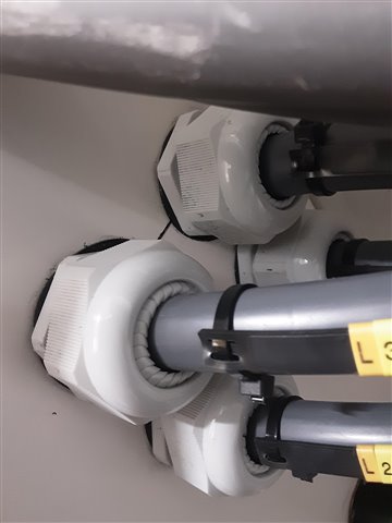
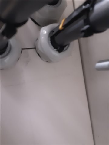
The panel board is supplied via single core double insulated 150mm conductors. As the picture shows, the cables enter through separate stuffing glands, but on closer inspection, the piece of metal in the centre has been slotted out so to be separate to the panel board itself.

As I have never seen it done this way before, could anyone confirm if this is compliant with 521.5.1 or if this could still cause an issue?

Regards

Mark

  • No issue provided the IP rating is preserved and the integrity of the DD has not been compromised. It is either that or cut a bigger aperture in the DB and fit an aluminium gland plate.

    JP

  • This sort of thing can reduce magnetic hysteresis losses in the steel, by increasing the magnetic path length around any one core, encouraging the current  to flow round the bundle instead. Topologically instead of multiple isolated holes you now have one, albeit an odd multi- dog-bone shape.

    In must be said that in thin sheet steel it is rarely necessary as the magnetic heating is not that much, but as the magnetic properties of knock out box steel are not very well defined, the regs suggest you do not put flow and return currents through separate holes, and this slitting is one way to achieve that.

    To recover the IP rating, it is possible to fill or cover the slots with another metal or indeed any material that is non-magnetic, brass braze or hard solder is one approach, but in less critical situations, filling the slots with glass-fibre, or epoxy resin or even mastic, is fine electromagnetically.  Mechanically that last one may not make the grade ;-)

    Mike

  • Or a brass one.

  • Morning Chris

    Yes brass can be used.

    I was doing an inspection with a colleague on a Form 4 panel and thermal imaging the panel at the same time.  The panel was supplied from a TX  on the other side of the switch room in AWA singles. The AWAs entered the panel through a steel gland plate and the load current was 800A+  per phase. I thought a picture plus a thermal image picture would make a great teaching aid. Not so the cable entry area was the same ambient temperature as the whole panel which was a bit of a surprise. I used to inspect this installation on a yearly basis and did the same every year for about 6 years and never found any sign of local heating on the panel. We found loose terminations in other places in the building which reduced in number over the years.

    JP

  • I'm not too surprised.

    The magnetic heating of sheet steel is often second place to effects of the electric currents that try and flow along the aluminium armour wires and though the glands them selves in a loop parallel to the main phase currents. No amount of dog-bone slotting helps that, but either a much better conductive plate - perhaps aluminium, or a much less conductive plate, such as fibreglass or paxolin, will do the trick in terms of that source of heating. Which is best depends how the earthing arrangement you need is expected to work..

    Be aware that brass, like steel,  is a pretty poor  conductor, both electrically and thermally, compared to aluminium or copper..

    The magnitude of the magnetic problem, the only one solved by the slotting like this, is very material dependent, and as I said above, often almost non-existent in the cheaper steel used for  knock out boxes.

    Mike.

  • Mike

    The AWAs are usually gapped at the Tx end by the DO, and were in this case, and earthed at the panel end to avoid circulating currents. When I say gapped the DNO cut back the AWA armour by at least 300-500mm and wrap self amalgamating tape over the aluminium ends. 

    A separate earthing conductor is run out from the Tx. to the panel. Or at least should be I have found plenty of installations unearthed and 3 very large installations, one new and one first installed in 1958 un-earthed despite the fabricated certification and reports. One was a London Underground station. The new installation had AWAs and a separate earth in to the switch room from the Tx. but no connection of the earthing conductor to the MET. Also no main protective bonding and many other defects and non-compliances despite what was written on the fabricated test certificates.  

    JP

  • plenty of installations unearthed and 3 very large installations, one new and one first installed in 1958 un-earthed despite the fabricated certification and reports. One was a London Underground station.

    Ha !  The world of regs and the one folk live and work in are really quite different places aren't they. I have never seen a big site like that but I have seen more than one house off-earth.

    The odd thing is that once it has been installed, quite often no one actually notices for years - a success for the equipotential concept I suppose - all the CPCs joint to each other, but not to the big MET.. In a large site it may well pass a final circuit  R2 wander test as well depending where the wander lead is clipped on to.

    Sorry yes - I should be clearer, when I talk about armour current that is only a problem with installations with metal glands and plates at both ends, and in some 'special facility ' cases, that can be mitigated on a long run by crossing over the armours 1/3 and 2/3 of the way along so all the ends see the same voltage having spent 1/3 of the distance in close proximity to each phase, so it all cancels.  Not commonly needed - insulation at one end or the other is  much easier and normally enough (not both though or there is no  ADS for mechanical damage. Mind you, like the off earth, I bet there are a few with unconnected armour at both ends.)

    Mike.