Harmonics in 3-phase systems with no neutral

I have an EV charge point that is a 3-phase 4 wire system that comprises of no neutral (L1/L2/L3/PE). As per the datasheet, the third harmonic content of the line current is rated as approx. 8% (THDi ≤8%).


Question: with no neutral, where does the current arising from the third harmonic content of the line current flow? My best guess would be through the protective conductor – which is not ideal as I’m trying to prevent unwanted tripping of the upstream 30mA RCD device.


thanks for the help.
Parents
  • One of the nice or nasty things about 150Hz, is that is looks the same on all 3 phases, so if the 3f zero crossing is say 10 degrees after the 50Hz one, on one phase it will also be on the other 2 phases. So if the loads on all 3 phases were exactly equal, the 3 F, 9F components etc would all cancel. However this does not mean that you need a neutral to have distortion to the line waveform that gives a 150Hz repeating feature. In fact the 3 phase/ 6 diode bridge does it depressingly well because in reality the 6 diodes are never quite equal. So the answer is that the 3 F current in any one phase is imperfectly cancelled by the nearly corresponding 3F currents in the other two, and when the 150Hz current is   is 5-10 percent of the 50Hz RMS current then that 3F component is  is 30-20 dB down and is about the sort of thing you get with no special precautions taken.  I would expect any 3F currents flowing in the CPC to be a lot lower.

    Mike.

  • Does the impedance change due to harmonic currents in the CPC, and how does this affect the MCB tripping depending on its type and characteristic, is there a risk of failing to protect against overload or fault currents?

    Mike will probably give you a much more accurate answer, but in my head I think of the current as being a mixture of frequencies, each one has its own impedance (1/2πfL etc) so the basic 50Hz fault current flows just like it always does, but the higher frequency components get attenuated in different ways.

      - Andy.

  • The impedance is not a single value at all frequencies - at DC it may be a short circuit, at 50Hz , and at low frequencies a low inductance, but at some frequency the line will be resonant and a very high impedance, and then above t hat  it will look capacitive, Now unless you design trans-continental distribution or railways, at power frequencies this is negligible - you may assume a simple R-L series network for the fault loop. The fact that the harmonics see a different impedance to that seen by  the fundamental means that the waveform changes along the line. 

    It is as if the waveform is split into its  frequency components and each of those components makes its way through the transmission line or inductor /capactitor or whatever at its own speed set by the impedaces  it sees,  in blissful ignorance of the progress or otherwise of the other frequencies. Then at some point you sum the levels of the components that survive that far and recreate the new modified waveform. Clearly each capacitor or wire or inductor only sees the sum of the voltages and current of the various component waveforms that have got that far.

    (the maths chaps and us physics types call this method  "linear superposition", but I suspect that is no help at all, so I'll try not to mention it again....)

    So as a noddy example at one end you put in say 230V of 50Hz and 10V or 150Hz. But the line includes some inductive element so 50Hz sees 1 ohm, and the 150Hz sees 2.5 ohms so the harmonic current is not 1/23 but 1/(2,5*23). At the far end however you have perhaps a 10 ohm resistive load.  So 230-23 = 207 or so volts at 50Hz reach the load, but only 2.5 V or so of 150Hz.

    The high frequencies have been attenuated slightly. In pulse terms any sharp edge has been dulled and there may be overshoot or ringing as well depending on the phase delays between the harmonic components, which I have deliberately not bothered to mention.

    Can harmonics cause ADS to misfire - yes for sure but only in designs near the the edge or where the total harmonic levels are comparable to the fundamental.

    Mike.

  • Yes, harmonics can cause circuit breakers to misfire but also prevent them from tripping. How I see it, when non-linear loads draw current in abrupt pulses, rather than in a smooth sinusoidal manner, harmonic currents flow back into other parts of the power system. Since the peak of the harmonic current is usually higher than normal, circuit breakers may trip prematurely at a low current. If the peak is lower than normal, the breaker may fail to trip when it should. So the original post of "which is not ideal as I’m trying to prevent unwanted tripping of the upstream 30mA" do we agree that this potential dangerous condition if the it's possible the breaker will fail to operate and/or nuisance trip?

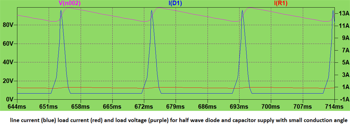
  • in principle,  but only with highly non-sinusoidal wave-forms - as you describe the rectifier inrush is a classic for this ,

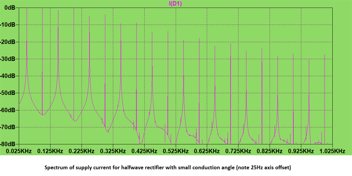
    in a single diode rectifier the 2nd and 4th are at the same strength as carrier,

    Time domain and

    Frequency domain

    And indeed a waveform like this where the 50Hz component is not the dominant can cause premature operation of the breaker, and problems with the neutral in 3 phase by non-overlapping pulses.

    Mike

  • but also prevent them from tripping.

    I'm not quite following the train of thought here. We usually expect circuit breakers (or fuses) to trip in three main circumstances - during faults (to protect conductors), during overloads (also to protect conductors) and for ADS (to give protection from shock). For faults before the equipment (i.e the ones BS 7671 is concerned with) the fault current will flow just as normal (and additional harmonic components won't detract from that current flow) so provided normal loop impedances etc are OK, then then circuit breaker should open at least as quickly as normal. For overload the thermal element of the MCB will see the total heating effect of the current which is a decent representation of the heating effect within the cables it's protecting - whether it's a steady sine wave or something contorted doesn't really matter - they effectively get integrated just the same. If the MCB trips for overload it should mean that the cable its protecting has already reached an undesirable conductor temperature -  so that's correct operation regardless of the waveform. ADS should be like other faults (other than it involves the c.p.c. rather than another live conductor) - so again the normal 50Hz fault current should flow (regardless of any additional harmonics) so the MCB should trip within normal times.

    For faults inside appliance (e.g after diodes in Mike's diagrams) then fault currents may well be affected - more due to to additional impedance of those components rather than harmonic currents per se (even a simple resistor would be a problem for ADS if using overcurrent protective devices for disconnection). That's really outside of BS 7671 territory (a problem for the particular appliance standard) but traditionally the "escape of the magic smoke" was considered to provide the answer (i.e. given a short circuit the diode would rapidly go 'pop - resulting either in an open circuit (i.e. providing disconnection) or a short (in which case normal earth fault current can then flow and then ADS performs as normal (if a little delayed). These days we'd probably incorporate a small residual current RCD to make sure.

      - Andy.

  • So therefore, harmonics can cause nuisance tripping or premature aging of the circuit breakers only?

  • So, to answer the question about the 30mA RCD device upstream going off when it shouldn’t. Yes, you could have this problem if you don’t use harmonic filters. I realise this is not the only problem that harmonics can cause. They can also damage other parts of the power system and make it less efficient. But the circuit breaker not working is not one of them.

  • inclined to agree - I cannot see a situation where a peaky waveform causes something to not trip when it should, but a higher peak to average may lead to both breaker and circuit being more stressed than the nameplate rating based on averages or RMS values suggests. And there lies one of the reasons that large loads without power factor correction either by L-C filters or switch mode active methods are not permitted ;-)

    More on those active methods is described here.

    https://www.st.com/resource/en/application_note/an523-understanding-power-factor-stmicroelectronics.pdf

    Mike

  • A 300 mA type B 4 pole 100 Amp RCD that was protecting an industrial batch washer tripped unexpectedly after 2 days of operation today. The RCD was faulty and could not be reset even with the load disconnected. I replaced it with a new one today and it resumed normal operation. There was no clear indication of what caused the tripping. It could have been harmonics? Probably more likely a short circuit or a voltage spike.

  • Given that the RCD was faulty, did it need anything to cause the trip?

Reply Children
  • Would not reset after the trip had occurred 

  • without opening it it would be hard to say - but an RCD that size probably has electronic amplification between the sense coil and the trigger mechanism, which is probably firing a fairly bosky solenoid actuator  with a triac or power transistor. I'd bet, but not very much that most likely a mechanical issue, followed as next likely by the trigger electronics having failed dead short, so the actuator fires as soon as power is applied. The latter sort of fault is more likely to be spike induced.
    Mike.