Repost - Earth Rod not taken account in TN systems

Hi All,

I realise the function of the earth rod in a TN system is to provide a close reference to true earth for the neutral

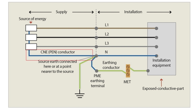
The thing that has confused me slightly is the TNCS PNB, which has an earth rod located at the consumer end. When i looked at the old forums there was a debate between whether this was TNCS or TNS, as the neutral carries no current due to the earth rod, and therefore by definition cannot be a combined conductor. If the current is not dissipated into the ground via the rod, why would no current flow in the neutral of this system prior to the rod

Thanks in advance

EDIT: My question wasn’t phrased very well and I’ve tried to clean it up for future readers, but i think this is the correct summary.

Fault current CAN flow between the neutral/earth link and the neutral point of the transformer in a PNB earthing arrangement. The previous forum posters were essentially saying is that even though though the link is remote, fault current will still flow in the CNE cabling, but we can note that it also would in a pure TN-S system but more likely an internal section of busbar within the TX and the neutral bar, instead of external cabling and by that logic TN-S would be a form of TN-C-S if semantics were involved.

Link to thread
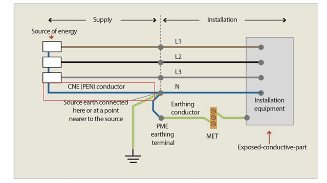
 What earthing arrangement is this? 

  • PNB is not a TT system - it's a TN system, which means that the fault current to PE (exposed-conductive-parts) travels back to the transformer neutral either via the separate protective conductor all the way (TN-S), or the separate protective conductor then the PEN conductor (TN-C-S).

    PNB comes in some different variants, some of which are shown in ENA Engineering Recommendation G12/5, although the actual diagrams on some DNO's web-sites provide much more insight into real arrangements of PNB.

    The difference with a PNB (TN-S variant) from a TN-S system, is that the electrode (and its connection to the Neutral) is not immediately adjacent to the LV side of the transformer, but happens some distance from the transformer (typically around 8-10 m or more), simply because the fault conditions on the HV side of the transformer will not permit the HV and LV earths to be connected at the transformer pole. In the TN-C-S variant, typically the earthing of the neutral happens at the first customer rather than along the LV line.

    Compare with TT system, where the fault current travels back to the transformer neutral down the consumer's separate PE conductor, then through the consumer's earth electrode, the general mass of Earth, then the distributor's earth electrode - hence the 'typical' quoted Ze for 100- A supplies being 21 ohms (not including consumer's earth electrode resistance).

  • Hi, I did try and answer your previous post. The absence of current flow in the neutral of this system before the rod is due to the lack of potential difference between the neutral and the earth at that point. The PEN conductor is earthed at multiple points along its length, so it has a very low earth impedance. Consequently, there is no voltage drop along the PEN conductor, and no current flow between the PEN and PE conductors.

  • If you are referring to a TN-S system, then the fault current does not go through the ground at all, and it is dissipated as heat within the cabling until the ADS occurs. The earth rod does not impact the loop impedance calculation. If you are referring to a TN-C system, then some fault current goes through the ground via the earth rod, but it is still mostly dissipated as heat within the cabling until the ADS occurs. The earth rod does impact the loop impedance calculation. If you are referring to a TN-C-S system, then no fault current goes through either of the earth rods at both ends of the supply cable. The fault current is dissipated as heat within the cabling until the ADS occurs. The earth rods do not impact the loop impedance calculation.

  • Hi AMK, Thankyou firstly for the in-depth answer. 

    I think you may be on to something with the lack of potential difference between the star point of the TX, and the consumers neutral-earth link, and potentially explains why DNOs limit the length of this system to 40m to reduce the possibility of a rising voltage. For clarity its TNCS PNB I’m thinking about, I’ve highlighted the leg in the image below.

  • Thanks Graham, that’s a helpful response. Ill look into those more detailed DNO images

    The reason my confusion came about from looking at an old forum discussion on whether PNB was actually TN-S or TNCS with well established members arguing that the CNE before the neutral earth link didn’t actually carry fault current. The leg I’m thinking of is attached in an image

  • Hello Fiftyhertz, I appreciate your reply. BlushThe lack of potential difference between the star point of the transformer and the consumer’s neutral-earth link is correct. This is because the PEN conductor is connected to earth at both ends, creating a low impedance path for fault currents to flow. I agree this also explains why DNOs limit the length of this system to 40m, as longer cables may cause voltage drops and unbalance along the PEN conductor, affecting the supply quality and reliability.

  • I believe in the PNB arrangement, its only got the link at the consumers end of the installation, and this replaces the connection to earth at the star point in the TX spill box

  • There is a article titled “PNB arrangements – a new earthing arrangement for some DNOs”The article explains that the lack of potential difference theory may not hold in some cases, such as when there is a fault on the distribution network or when there are parallel paths for fault currents. Therefore, it is important to follow the guidance and precautions given by the DNO when installing or altering an electrical installation with a PNB arrangement.

  • One has to be careful when discussing faults to earth- there are two very distinct cases.

    1) We may mean faults to the earthed chassis of a piece of equipment,  such as when a washing machine or or a kettle fails - then the current is via the CPC, and in a TN-'x' where x is anything, there is an all-metal path from the live phase of the transformer to the fault, and on in the other side of the fault  an all metal path  of comparable resistance all the way back to the other side of the transformer. So 100A fuses can be blown, and traditional ADS works,

    2)  But there is a second class of 'fault to earth' even on TN-x which is where there is a fault to terra-firma earth but not the circuit CPC, such as the cut lawnmower cable  or damage to a double insulated tool that exposes a live part (garden tools are especially vulnerable) These faults always include the terra-firma earth path, rather than the CPC, and sometimes include a hapless person as well. Here the only reliable protection is the RCD,

    (Note that In TT the return path from the CPC also includes tens to hundreds of ohms of wet soil , and even with a solid  metal contact type fault the current will probably fire an RCD but only the smallest of fuses or MCBs...

    There is also another related nasty case worth a mention.

    Consider that the supply side earth electrodes may well only just make the 21 ohms for a lone 'pole pig' transformer in the country.

    Then if there is a fault that pulls one phase down much better than that - perhaps a fault from live to something that is a far better electrode than the DNOs one - and one  classic is the metal bodied barn with pile driven metal footings.. Now it is not the faulty installation that gets pulled to earth, but rather the phase,  Or to be more accurate, the full P-N voltage is split between the 2 electrodes and the ground between them and more of the volts are dropped in the ground near  the electrode with higher resistance. So everything that is earthed, or at least 'neutralled' to the supply CPC is now at some voltage well above terra-firma, and tingles and shocks will be reported from things in the installation that are working perfectly, while apart from a higher than normal meter reading, the fault may not be noticed for some time. Again RCDs save the day.

    Mike

  • In the above diagram you posted, the electrode is not on the consumer side, but the distributor's side.

    One of the issues in the industry, is that people have been taught that if there is an electrode at the consumer's premises, it's always TT. Whilst was easy to remember when passing exams, sadly, it is NOT ALWAYS the case (in fact, never was).

    The giveaway, is that there is an earthing conductor between the distributor's earthing terminal and the MET. Have a look at Regulation Group 542.1.2, which provides the clues you need. in TT and IT systems, the earthing conductor is connected to the consumer's electrode(s) ONLY, whereas in a TN-C-S or TN-S system, the earthing conductor connects to the distributor's earthing terminal.

    PNB of the variant shown in your diagram above (or as used in installations with a private transformer, and earth electrodes connected to the neutral at the main switchboard), is only one example of where a TN system has additional earth electrodes. An additional consumer's earth electrode may be provided by the consumer in their installation for any TN system (in fact, BS 7671 now has a firm recommendation for this, see Regulation 411.4.2, last para). Where the connected mode earthing arrangements are TN, additional earth electrode (or electrodes) is likely to be a firm requirement for an installation with island mode capability because of Regulation 551.4.3.2.1.